CANopen EDS File Explained - A Simple Intro [2025]

Need a simple intro to the CANopen EDS file (Electronic Data Sheet)?
In this tutorial we explain the Electronic Data Sheet (EDS) and Device Configuration File (DCF) incl. the basics, syntax, software tools - and the link to CAN bus DBC files.
To get practical, we also include raw CANopen data and related EDS/DBC files - which you can load in free open source software/API tools.
Get ready to fully understand CANopen EDS files!
In this article

What is an Electronic Data Sheet (EDS)?
The CANopen Electronic Data Sheet (EDS) is a standardized text file format defined in CiA 306-1. It acts as a digital template for the Object Dictionary (OD) of a CANopen device, specifying the objects supported by the device.
In particular, the EDS includes the following info:
- Communication specific objects as per CiA 301
- Device/interface specific objects as per the device profile
- Manufacturer-specific objects
The CANopen EDS essentially serves as an electronic description of a specific device from a specific vendor. The EDS can be loaded by CANopen software/API tools to help configure devices, manage networks and interpret raw CANopen traffic.
The EDS is normally provided by the device vendor to enable easy integration of the device into a larger network.


DCF (Device Configuration File)
The Device Configuration File (DCF) is a specific incarnation of a device Electronic Data Sheet (EDS). In a CANopen network it is common to have several devices with the same EDS. As part of the CANopen network configuration, each of these CANopen devices are assigned a specific node ID (and thus unique CAN IDs for communication) and a specific bit-rate. This information is required in order to translate the 'general-purpose' EDS into a DCF, which is ready for installation. In addition, the DCF may also add specific values for other objects in the EDS.
For example, a CANopen bus may have five IO modules connected to the same CAN bus, all of them sharing the same EDS. To enable communication, the devices must receive unique node IDs (to avoid ID collision) and their bit-rates must be set to match the CAN bus in which they are integrated.
Other objects that are often customized via the DCF include the PDO payload mapping, COB-IDs and manufacturer-specific settings related to e.g. calibration parameters or limits.
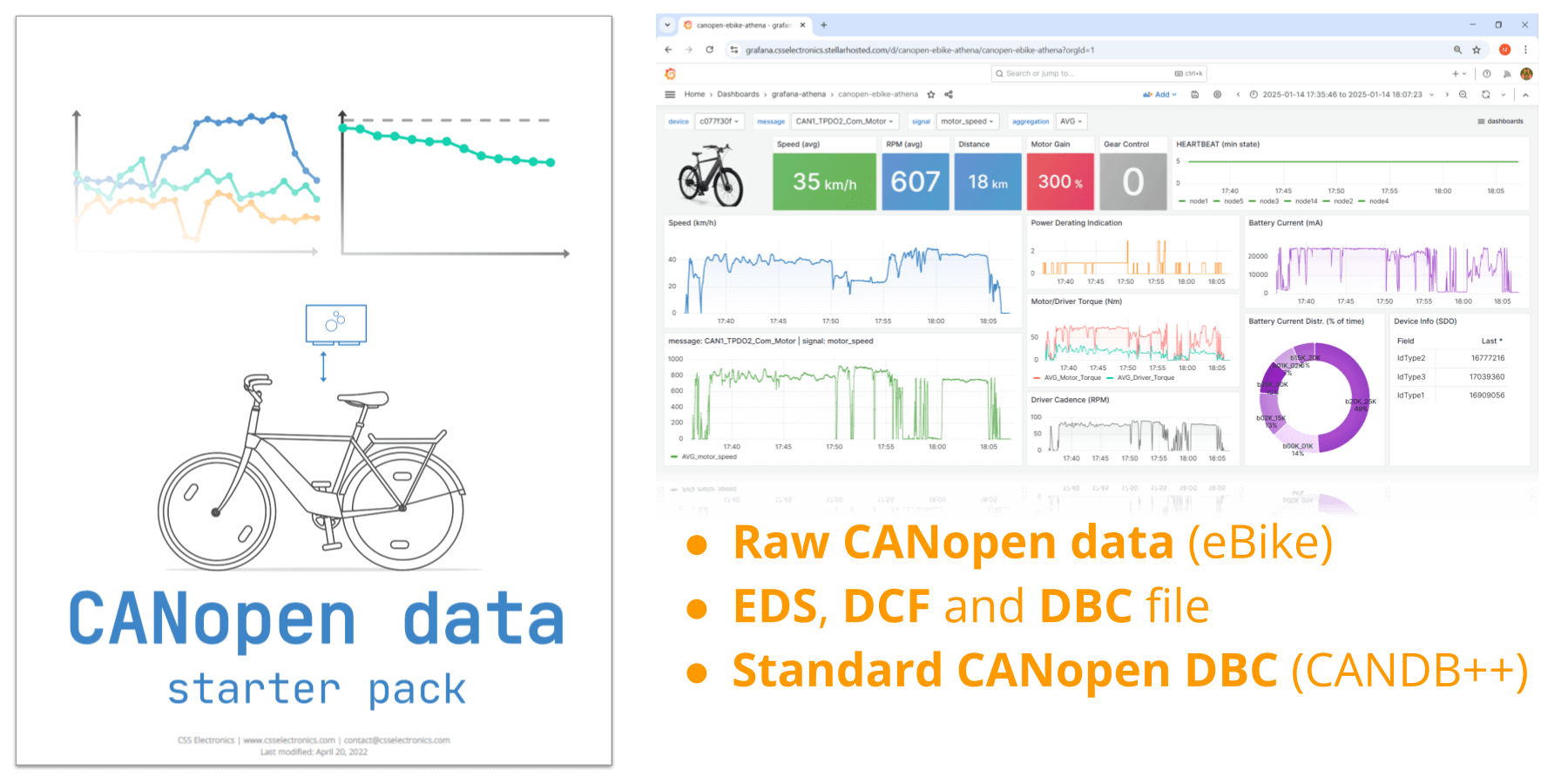
Get the 'CANopen data pack'
Want to work with real CANopen data?
Download your 'data pack' now:
- Raw CANopen data from eBike (recorded with CANedge)
- Device specific EDS and DBC files
- Standardized CANopen DBC file (from CANDB++)
EDS syntax
In practice, you will normally use an editor tool to load/create/edit/export an EDS file. This helps ensure valid syntax and to avoid consistency errors.
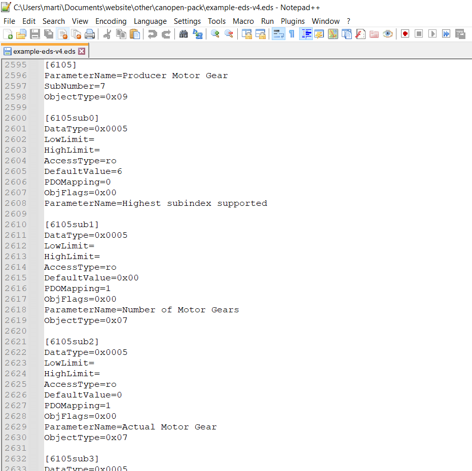
However, to properly understand EDS files we believe it is relevant to review the raw file syntax. In this section we outline the most important sections of the EDS with outset in the device specific EDS file in our CANopen data pack. You can open this file in Notepad to follow each example below.
General syntax explanation
The EDS is ASCII-coded and limited to ISO646 characters. Each line must not exceed 255 characters. Beyond this, the EDS is composed of 'sections', each of which have the following format:
keyname1=value1
keyname2=value2
...
- Section names and keynames are not case sensitive
- Section names and keynames are interpreted as strings
- Leading/trailing spaces in values are ignored
- Integer values can be written as decimal (e.g. 10), hexadecimal (e.g. 0xA or 0x0A) or octal numbers (e.g. 012)
- String values are stored without quotes
- Formulas may be used in values, e.g. IntEntryValue = $NODEID { "+" number }
- Comments may be included (must start with a semicolon)
- Empty lines may be included
- Sections may appear in any order in an EDS
- Keynames may appear in any order in a section
- Sections/entries described in CiA 306-1 are mandatory
1: EDS metadata
The EDS includes general file and device information that is not directly linked to the CANopen Object Dictionary objects.
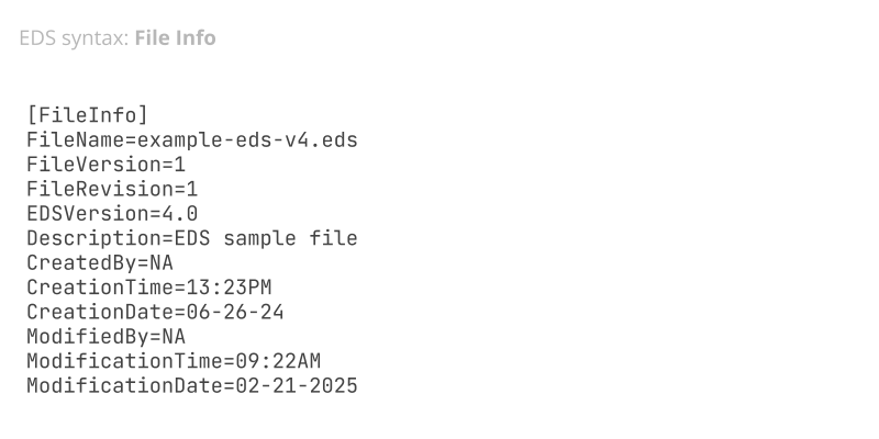
1.1: [FileInfo] section
This section describes the EDS file itself, useful in e.g. revision management. Fields include the file name, version, EDS version, creation/modification dates, author name and a description.
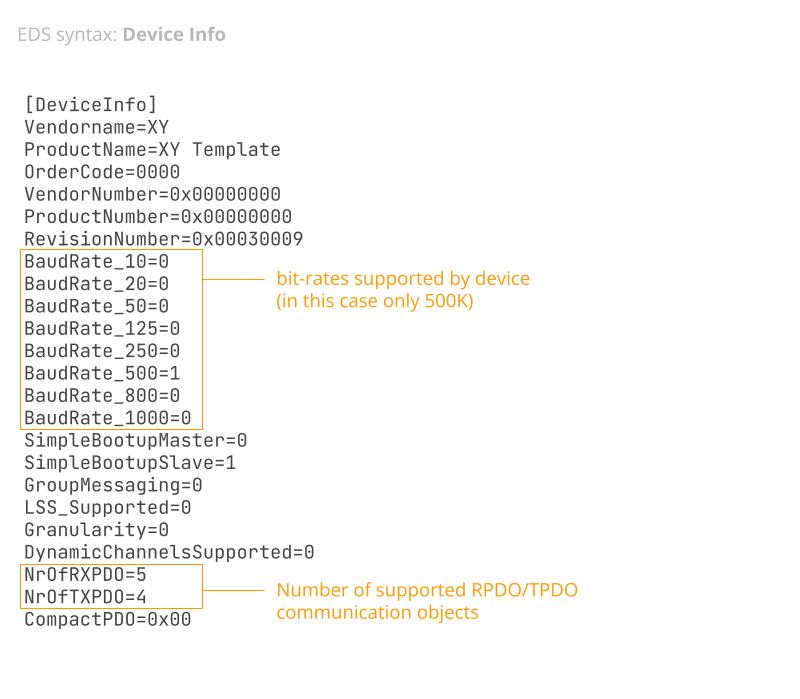
1.2: [DeviceInfo] section
Here, the EDS provides general details on the device including vendor name/ID, device name/code and version.
The section also includes entries reflecting what functionality the device supports, with the value being 0 or 1 depending on whether the device supports the specific functionality. This includes 8 CAN bus bit-rates in the range 10 kbit/s to 1000 kbit/s, support for multiplexed PDOs (via the GroupMessaging entry) and support for LSS (Layer Setting Services) as per CiA 305. LSS e.g. enables CAN based configuration of the device node ID and bit-rate. In addition, this section also details the number of supported receive PDOs (RPDO) and transmit PDOs (TPDO).2: EDS object lists
These sections list the objects supported by the device, referencing the 16-bit object indices. Each index can be looked up in the EDS for details. Objects are grouped by mandatory, optional and manufacturer specific.
Note that the Object Dictionary is often split in a slightly different way as per the illustration, i.e. by data types (0x0001-0x025F), communication objects (0x1000-0x1FFF), manufacturer specific objects (0x2000-0x5FFF), device profile objects (0x6000-0x9FFF), interface profile objects (0xA000-0xBFFF) and reserved (0xC000-0xFFFF). This is also how most EDS editors group the objects.
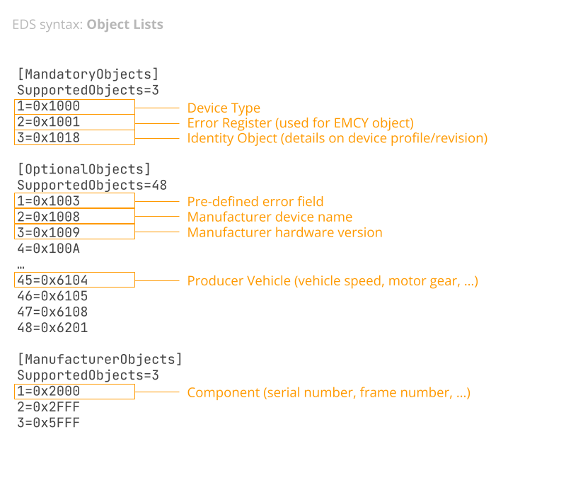
2.1: [MandatoryObjects] section
This lists the mandatory objects supported by the device as defined in the Object Dictionary section of the CANopen standard in CiA 301. The list must include 0x1000-0x1001 and typically includes 0x1018 (mandatory from CANopen 4.0).
Object 0x1000 describes the device type including a 16-bit field describing the device profile or application profile, followed by another 16-bit field with additional information. In many EDS files this is left blank with a default value of 0. Object 0x1001 reflects an error register used in storing internal errors that may be communicated via the CANopen EMCY message. Finally, 0x1018 is the identity object which contains information about the device profile/revision that may be relevant to the communication.
2.2: [OptionalObjects] section
This section contains all other objects in the range 0x1000-0x1FFF and 0x6000-0xFFFF. Most EDS files include 10-60 optional objects to expand the functionality and configurability of the device. The 'communication object' range 0x1000-0x1FFF may e.g. include objects like 0x1010 for storing parameters, 0x1011 for restoring them, 0x1014 for the EMCY communication object and 0x1016 for the HEARTBEAT object. The 'device profile' range 0x6000-0xFFFF may include e.g. sensor-related objects like speed, gears, temperatures etc.
2.3: [ManufacturerObjects] section
This contains manufacturer-specific objects in the range 0x2000-0x5FFF and can be used for e.g. specialized sensor info.
3: EDS object descriptions
Most sections in an EDS reflect specific objects. Below we outline the general syntax and key sections related to PDOs.

3.1: Object syntax
In the object section, the section name equals the object index in hex, e.g. [1018] for the object 0x1018. A 'structured object' has sub-indexes represented as separate sections e.g. [1018sub1] for index 0x1018 sub-index 0x01.
Within an object section, the following keynames may be used:
- ParameterName: Name of the parameter
- ObjectType: Object code - if missing it equals 0x7 (VAR)
- SubNumber: Number of sub-indexes (if any)
- DataType: Index of data type in the Object Dictionary
- LowLimit/HighLimit: Limits of the object value (if applicable)
- AccessType: Access rights for the object
- DefaultValue: Provides a default value for the object
- PDOMapping: Indicates if the object can be mapped to a PDO
- ObjFlags: Optional assignment of special behavior
As evident, SubNumber must show the total number of sub-indexes if any exist, which includes sub-index 0x00 (sub0). When sub-indexes are used, the first sub-index entry (sub0) always describes the 'number of entries' with a default value equal to the highest sub-index. While most objects describe consecutive sub-indexes from 0x00 to this highest value, that is not required. As such, an object may e.g. have two sub-indexes (SubNumber=2) where the first sub-index 0x00 specifies a DefaultValue=0x4, meaning that the next (and last) sub-index would be sub-index 0x04 (sub4) - even though there was e.g. no sub1, sub2, sub3 in the EDS for this object.
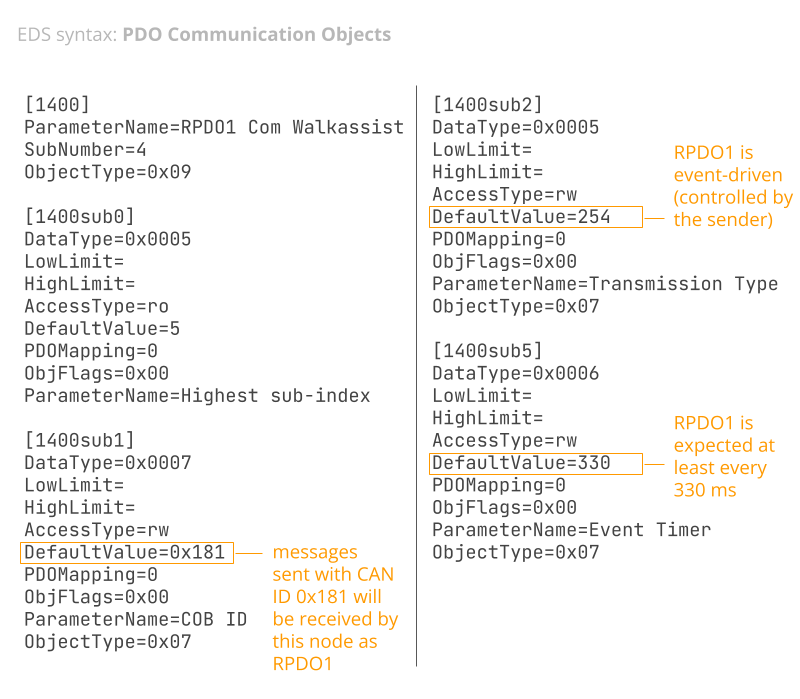
3.2: PDO communication objects
Most EDS files include objects related to the receive/transmit PDO communication objects with indexes 0x1400-0x15FF and 0x1800-0x19FF, respectively. Typically an EDS only describes a few of these, however.
These objects describe communication-related parameters, including e.g. the COB-ID (and hence CAN ID) used for each PDO. In most EDS files the COB-ID will have a default value specified that is a function of the node ID, e.g. DefaultValue=$NODEID+0x180 for Transmit PDO 1.
From a data logging perspective, the primary insight to extract from this section will be what COB ID is used for each transmit/receive PDO (assuming the user also has information on the specific node ID used by the device).
Note that if bit 31 of the default COB-ID is set to 1, the PDO is 'disabled'. See e.g. below example:
ParameterName=COB_ID
ObjectType=0x7
DataType=0x0007
AccessType=rw
DefaultValue=$NODEID+0x40000180
PDOMapping=0
LowLimit=0x40000181
HighLimit=0xFFFFFFFF
ObjFlags=0x0
[1801sub1]
ParameterName=COB_ID
ObjectType=0x7
DataType=0x0007
AccessType=rw
DefaultValue=$NODEID+0xc0000280
PDOMapping=0
LowLimit=0x40000281
HighLimit=0xFFFFFFFF
ObjFlags=0x0
Here, 0x40000181 equals 0b01000000000000000000000110000001 with bit 31 set to 0. If viewed in an editor, this PDO will be displayed as 'enabled'. The same would be the case if the PDO default value was e.g. 0x181 or $NODEID+180. In contrast, 0xc0000280 equals 0b11000000000000000000001010000000. Since bit 31 is 1, this PDO will be marked as disabled by default.
This method can help communicate which PDOs are going to be supported/used by the CANopen device by default. In most EDS files, all PDOs are enabled by default as will be clear by their COB-IDs using 11-bit default values.
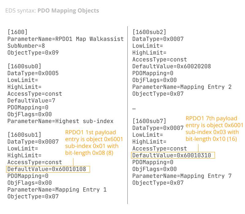
3.3: PDO mapping objects
This section is highly relevant for data logging purposes as it describes which objects are packaged in which PDOs. In many ways, this information is similar to the core message/signal encoding details found in CAN databases (DBC files).
The receive/transmit PDO mapping objects use indexes 0x1600-0x17FF and 0x1A00-0x1BFF, respectively. As with the communication objects, most EDS files only outline a few.
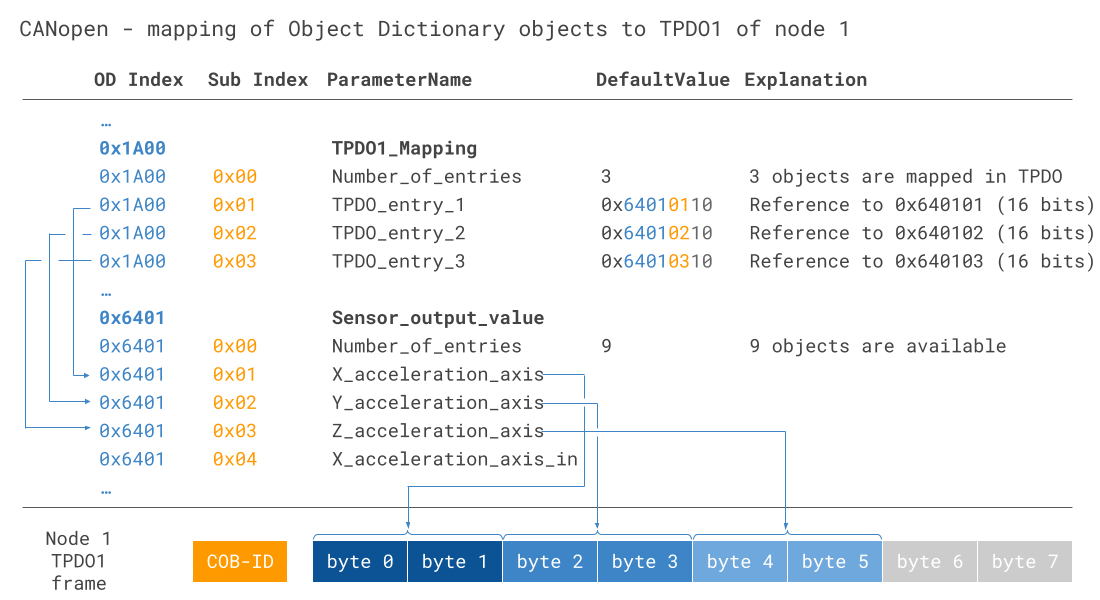
Each PDO mapping object includes a sub-index for each mapped object. These sub-indexes may have dummy ParameterName values like 'Mapping Entry 1'. The important keyname here is the DefaultValue. This value reflects the index, sub-index and bit-length of the object that is mapped within the payload of this PDO. For example, DefaultValue=0x61010108 refers to the object 0x6101 sub-index 0x01 with a bit-length of 8 bits aka 1 byte. With this information, it is possible to identify the full mapping of a specific PDO data payload and determine the bit-start and length of each object (aka CAN signal). Note that some mappings may reference dummy objects to pad the payload to 8 bytes.
See also below visual illustration of how the PDO mapping works - further details can be found in our CANopen intro.
DCF syntax
The DCF syntax is almost identical to the EDS syntax. If you open an EDS in an editor tool, you can export it to a DCF. If you do so without any further modification, the resulting DCF will be equivalent to the EDS, but with some minor changes.
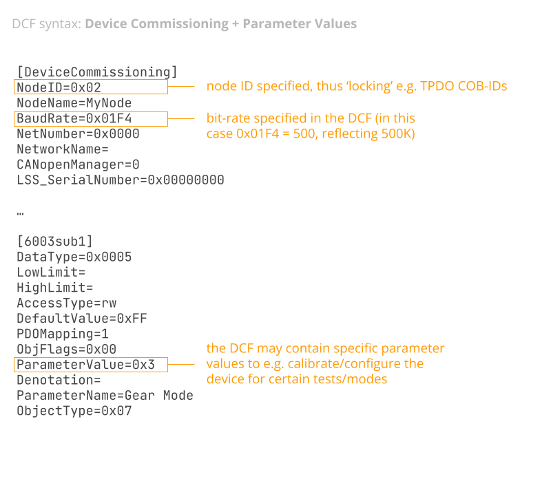
1: DCF device commissioning
The DCF adds a new section called DeviceCommissioning. This assigns a concrete node ID and bit-rate to the device, enabling installation into a specific system.
2: DCF parameter values
Beyond this, each object will have a new keyname called ParameterValue. This reflects how the DCF serves as an installation-specific version of the more generic EDS, allowing users to e.g. set specific limits, calibration values etc. For most objects this may be left blank, but if populated it must be set in accordance with the ObjectType and DataType.
How to get the EDS?
CANopen EDS files are often provided by the manufacturer to the company that is integrating the device into a larger CANopen network. As such, if you are the manufacturer or integrator, you should have access to the EDS (or be able to request it). The device integrator will typically use the EDS to create one or more DCF invocations as part of configuring a larger system that may include multiple devices.
If you are trying to get the EDS for a device when you are not the manufacturer/integrator, you will normally need to reach out to them to request it. In some cases this is possible, e.g. by signing a non-disclosure agreement (NDA). Alternatively, you can attempt to reverse engineer the data as per our CAN sniffer article - though this is fairly complex.


If you are simply trying to record data from a single CANopen device, you will normally only need one EDS/DCF - e.g. if you are using a sensor-to-CAN module.
However, if you are looking to understand an entire CANopen network with several devices, you may need to get multiple EDS files (one per device type) in order to interpret the full set of messages being communicated on the network. You will also need to know what devices have been assigned which node IDs in order to fully understand the communication.
CANedge: CAN/LIN data logger
The CANedge lets you easily record raw CANopen data to an 8-32 GB SD card. The device can record data as a silent CANopen sniffer and/or transmit requests like a CANopen master/client. You can decode the data via free software/APIs.
CANopen logger intro CANedgeEDS software tools (editing & processing)
Software that uses EDS files can be split in two groups: Editing & data processing.
EDS editor tools
As shown, you can create and edit EDS files with a simple text editor like Notepad. However, for GUI/API editing, consider below alternatives:
- Vector CANeds: Vector's free CANopen EDS explorer lets you open/edit/export your EDS/DCF and is great at identifying consistency errors
- CANopen Architect Mini: This free tool lets you open/edit/export EDS/DCF files. It is a bit simpler-to-use than CANeds, but has some limitations in the free edition
- CANopenEditor: This open source EDS editor offers similar functionality as the above and a nice visualization of the PDO payload mapping (get it via the Releases tab)
- canopen: This open source Python library lets you open/edit/export EDS files programmatically, which can be useful in automation routines and data analyses
- canmatrix: This open source Python library lets you convert CANopen EDS files to e.g. DBC files (more on this below)


CANopen data processing tools
Most CAN bus data processing tools support EDS and/or DBC files for decoding data. Below we list tools that can be used with the CANedge CAN/LIN data loggers:
- asammdf GUI: The asammdf GUI lets you load raw CANopen data in MF4 files and decode it via DBC files - as well as create quick plots, analyses and exports
- MF4 decoders: Our MF4 decoders let you DBC decode raw CAN data to create Parquet data lakes - ready for e.g. Grafana dashboards (see our CANopen example)
- MF4 converters: Our MF4 converters let you convert your raw CANedge MF4 files into other formats, e.g. for loading in Vector/PEAK tools with direct EDS support
- Python API: You can decode and process your CANopen data with our Python API using DBC files (or EDS files by parsing these via e.g. the canopen/canmatrix libraries)
 CANopen Architect Mini is great for viewing/editing EDS files
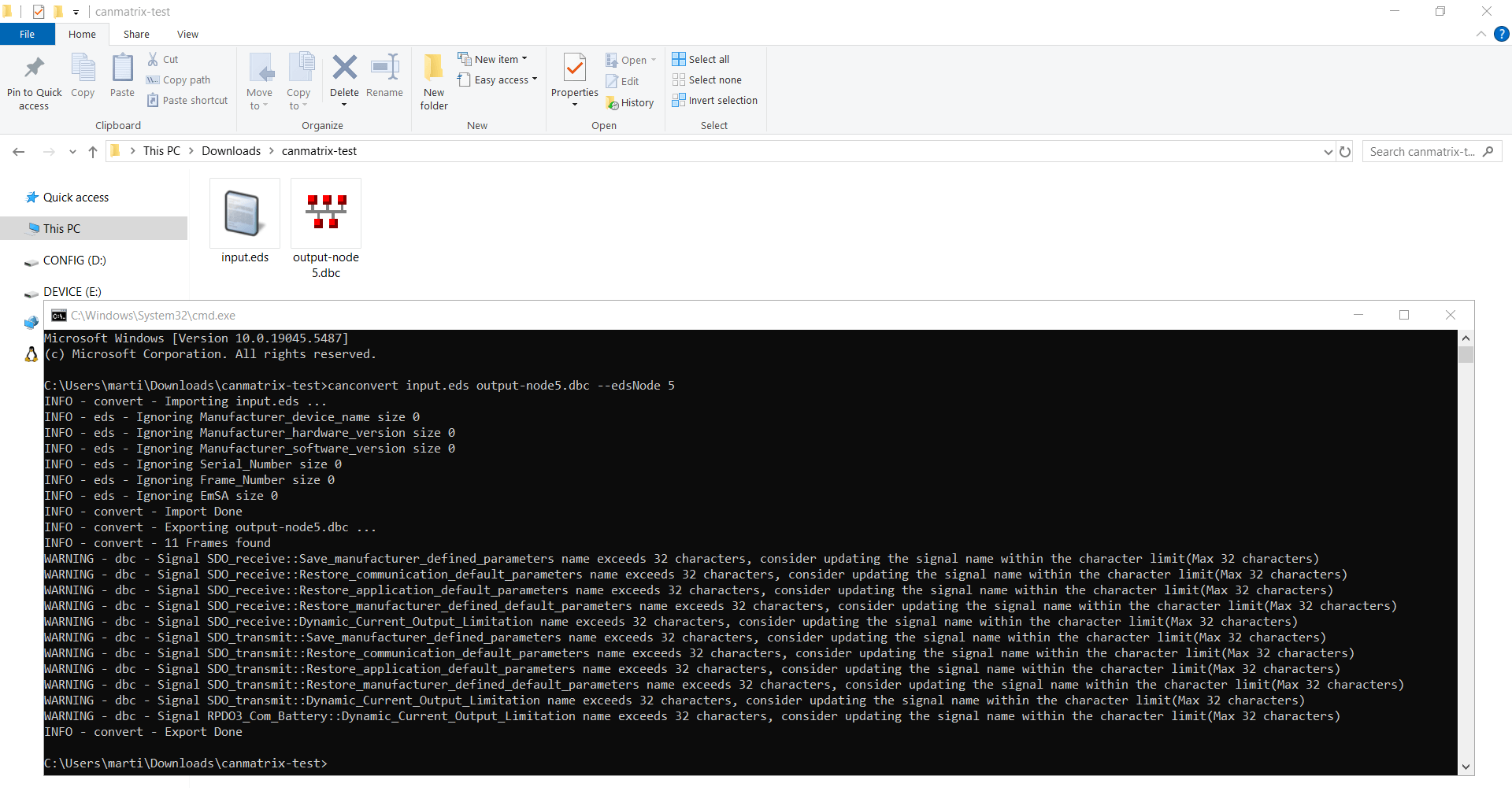 The canmatrix Python library lets you automate your EDS-to-DBC
conversion
The canmatrix Python library lets you automate your EDS-to-DBC
conversion
 asammdf is great for ad hoc CANopen data exploration and DBC decoding
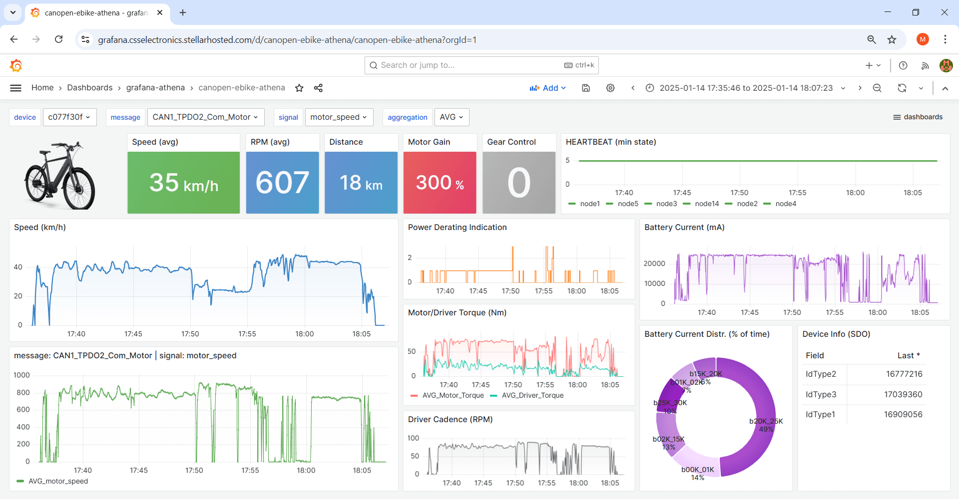 Grafana dashboards can be used to visualize decoded CANopen data
How to convert an EDS file to a DBC file
A popular tool for logging raw CANopen data is the CANedge, which can also offload it to your own server via WiFi/LTE.
If you have the EDS file(s), you can use the CANedge MF4 converters to convert your raw log files into other file formats like Vector ASC or PEAK TRC. This lets you decode the data in tools that natively support EDS files.
However, many CAN software tools only support DBC files. We therefore focus this section on the link between EDS/DCF and DBC files - and how you can convert your EDS into a DBC file.
Note: You can automate the conversion of your EDS to a DBC via canmatrix as explained further below. However, we recommend going through our step-by-step explanation below to understand what happens under-the-hood in this conversion.


Decoding raw CANopen data is similar to other CAN based protocols and requires the same information:
- ID: Which CAN frame ID contains the CAN signal (aka object)
- Message name: The CAN message frame name
- Signal name: The CAN signal name
- Start bit: Start position of the CAN signal in the payload
- Length: Length of the CAN signal in bits
- Endianness: The byte order (by default Intel for CANopen)
- Scale: How to multiply the decimal value of the CAN signal bits
- Offset: By what constant should the CAN signal value be offset
- Signage: Whether the signal is signed or unsigned
- Unit/Min/Max: Additional supporting information (optional)
As we will show, all relevant info can be extracted from the EDS (with some limitations as explained below).
An important difference between CANopen EDS files and DBC files is the fact that the CANopen EDS does not contain information on how to scale/offset a CAN signal, nor what the unit should be. In DBC files, this information is provided as part of the signal-specific decoding rules.
This constitutes a challenge when attempting to decode CANopen data, whether this is done via the EDS or a DBC file. Our recommendation is to solve this by assuming a scale factor of 1 and an offset of 0. For many CANopen objects, this will result in the correct decoding, although we recommend reviewing your decoded data to confirm this assumption. In our experience, the EDS may also contain additional scale information in comment fields below some objects/parameters. Alternatively, if the objects relate to device specific objects you may find more details in the related device profile standard (CiA 4XX). In such cases, you can incorporate this information into your DBC file manually.
Example 1: Standard CiA 301 objects
As per our CANopen intro, many objects are standardized, incl. NMT, SYNC, TIME, EMCY and HEARTBEAT. CAN frames related to these objects can be decoded without access to the device specific EDS as they are fully described in CiA 301.
Vector's free CANDB++ DBC editor can produce a CANopen DBC that includes these objects, letting you quickly decode and visualize this data. The DBC does not require information about what node IDs are used on the network as it includes replicas of the various objects for the full range of potential CAN IDs (e.g. 0x701-0x77F for the HEARTBEAT).
When decoding CANopen data, you may want both standard and device specific objects. To manage this, simply store the standard objects in separate DBC file.
If we decode the raw data from our CANopen data pack with the standardized DBC we can see the HEARTBEAT messages for nodes 1-5 and 14 and the TIME message.
 Raw CANopen trace showing TIME and HEARTBEAT objects
 CiA 301 objects can be decoded via standard CANopen DBC

SDO vs. PDO decoding
You will often also want to decode data communicated via Service Data Objects (SDO) and/or Process Data Objects (PDO).
For example, your data of interest may be polled by a CANopen master node (or the CANedge itself) from various CANopen slaves via SDO upload requests. Here, the slave responds with SDO frames that contain the command byte, object index, object sub-index and the value of the requested object. This response can be handled in DBC files via 'extended multiplexing', using the initial 4 bytes as an extension to the CAN ID.
Alternatively, the data may be communicated in PDOs. Here, decoding is simpler as no multiplexing is involved - though you must determine the mapping of the PDO payload via the EDS.
Most CANopen objects of interest will be polled via expedited SDO transfer, as the payload can fit within the available 4 bytes of payload. In contrast, SDO segmented transfers and SDO block transfers involve multi-frame communication and require re-assembly in order to process the data payload. In the sections below we focus purely on the simpler expedited transfer method.

Raw CANopen SDO upload trace

 Plot of DBC decoded SDO upload responses (1 observation of each)
Example 2: SDO upload response
In the sample log file of our data pack, we observe a number of SDO upload request/response frames communicated between a client and server node. This can be found in the raw CAN bus trace by filtering the data for IDs 0x602 (receive SDO for node 2) and 0x582 (transmit SDO for node 2).
As evident from the data, the client requests the value of objects with index 0x1F56 sub-index 0x01, 0x02, 0x00 and 0x03. This is done via expedited SDO transfer as per our CANopen intro.
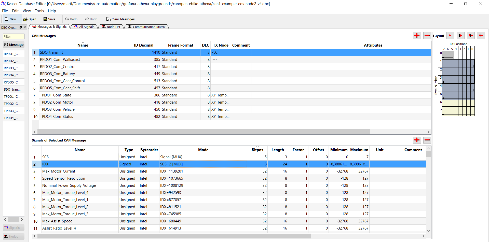
Let us consider how to create a DBC for the SDO transmit message. Here, the CAN ID is 0x582 and the name can be 'generic' (e.g. SDO_transmit). But to interpret the data payload found in the last 4 bytes, we must leverage the identification data from the initial 4 data bytes.
As per our CANopen intro, the 1st byte of the SDO upload response is the command byte. In this byte, we are interested in the 3 bit SCS (Server Command Specifier). The value of the SCS tells us if the response relates to an SDO download (= 3) or SDO upload (= 2). This lets us use the SCS as a multiplexor in our DBC to only interpret subsequent bytes when SCS = 2.
Next, consider the 3 bytes comprising the object index and sub-index (intel byte order). For index 0x1F56 sub-index 0x01, the value of this 24-bit signal is 0x011F56 = 73558. Like the SCS, we can use this index signal as another multiplexor to control the interpretation of the remaining bytes. This is called extended multiplexing in the DBC syntax. With this method we can uniquely interpret the last 4 data bytes based on the value of the 1st and 2nd-to-4th data bytes.
To decode the last 4 bytes, we look up the object in the EDS via the entry [1F56sub1] using e.g. Notepad or an EDS editor. This provides us with the signal name (= ParameterName) and bit length / signage (DataType = 0x0007 = Unsigned32).
We can now construct the full DBC file entry for the signal and repeat this for other sub-indexes. The final DBC file entry looks as illustrated and enables decoding as per the picture.
Note that in this case there is only a single request/response for each object - but in other use cases you may see a periodic request/response e.g. every 100 ms in order to poll a real-time parameter value like speed, temperature etc.
For details on extended multiplexing, see our intro to DBC files. Note that you do not need to fully understand the DBC syntax relates to this concept. Instead, we recommend using the canmatrix conversion method explained below - or to use a DBC editor like Kvaser's database editor if you wish to repeat these steps manually. For this purpose you can take outset in our sample EDS from the CANopen data pack.
Below you can see how the SDO_transmit message looks in the Kvaser DBC editor:
Example 3: Transmit PDO
From our EDS, we also see that various receive/transmit PDOs are defined for the vehicle with different objects mapped to the payloads as explained in our CANopen intro.
Via an EDS editor, we may identify that we are interested in TPDO3 as this contains speed, gear and odometer info.
To create a DBC file entry for this message, the first step is to identify the CAN ID. As per the EDS editor screenshot (and the EDS file), the COB-ID is specified to equal the base ID of 0x1C0 plus the node ID (DefaultValue = $NODEID+0x1C0). Notice that this differs from the 'default' COB-ID for TPDO3 messages, which would be 0x380 + node ID. This reflects the fact that the EDS has been modified to use custom COB-ID mappings to match the actual producer/consumer requirements of the network (see also our CANopen intro on PDO COB-ID mapping).
Since the TPDO3 COB-ID is 'variable', we need to know what node ID the EDS file corresponds to. In practical scenarios the node ID will either be known (e.g. by the device integrator), but if not then it may be 'guessed' via a bit of trial-and-error. Essentially you would test different node IDs starting from 1 and review if the results look sensible. In this particular case, we happen to know that the relevant node ID is 2 and the relevant TPDO3 COB-ID is therefore 0x1C2.
To understand the CAN signal mapping of this TPDO3 message, we can find the object 0x1A02, which provides the payload mapping details. We get the first signal entry in our DBC by looking at the entry [1A02sub1] corresponding to index 0x1A02 sub-index 0x01. The DefaultValue for this object is 0x61040110, a pointer to object 0x6104 sub-index 0x01 with a bit-length of 0x10 (16 bits). If we look up the section [6104sub1] of the EDS, we find that this parameter name is 'Vehicle Speed' and that the DataType is 0x0003 (= Integer16). With this information we can construct the 1st signal entry in our DBC file and continue to the next object referenced in the TPDO3 mapping.
Once completed, we can decode the TPDO3 as illustrated.
Notice here that the EDS file does not provide CAN signal scaling factors and hence there is no such field in the EDS editor either. However, if you open the EDS file in Notepad you will see a comment section below the Vehicle Speed and Odometer signals with further details on the scaling factors and units. While this information is not necessarily critical, it can be useful in further refining our DBC.
As explained, the TPDO COB-IDs depend on the node ID and to get the 'actual' COB-IDs matching our CAN bus data trace, we either need to 'know the node ID' (e.g. via information from the device integrator) or 'reverse engineer it' (via some trial and error testing). In this particular case we know the node ID is 2 based on information from the original device integrator.
For the receive PDOs, the EDS is a bit different as it provides 'static' default values for the COB-IDs of the RPDOs. In this particular case, it serves to reflect a specific COB-ID mapping used where node 2 is configured to consume data from a specific set of PDOs from a specific set of devices (in this case four from node 1 and one from node 9). In such a case it normally does not make sense to try and offset these COB-IDs by a specific node ID.
 Raw CANopen PDO trace (TPDO3 from node 2)
 Plot of DBC decoded TPDO3
Auto-convert EDS to DBC
Converting an entire CANopen EDS file to DBC can be very time consuming, as should be evident from the step-by-step walkthrough. Luckily, this can be easily automated using an open source Python library called canmatrix.
Simply install Python, open your command line and run below:
pip install canopen
You can now convert an EDS to DBC via your command line:
To edit/validate your DBC, we recommend to use a DBC editor.
Your EDS file most likely reflects the EDS of a specific device on the CAN bus, which has been assigned a specific node ID. If you have the corresponding DCF for the device, the node ID will be visible from that and you can then use this in the command line conversion above. Alternatively, it may be that you can get information on the relevant node ID from the device integrator or by a bit of trial-and-error.
It can be that multiple devices on the network use the same EDS, but have different node IDs. In this case you can simply run the command above multiple times, each time producing a separate DBC file for each node ID. We recommend explicitly including the node ID in the name of the DBC file in this case.
As evident from the CANopen data pack example, you may also experience that your EDS file contains a combination of 'dynamic' and 'static' COB-IDs for your PDO messages. In this case, canmatrix will only incorporate the node ID you parse into the 'dynamic' COB-IDs, while the 'static' COB-IDs remain unaffected by the node ID.
Unlike the DBC file, the EDS file format does not contain structured fields for the scale, offset and unit of CAN signals aka objects. To handle this, canmatrix simpy uses a scale factor of 1, offset of 0 and a blank unit for all signals. If you do have specific information on these missing fields (e.g. via comments in the EDS), you can of course update the DBC file accordingly using e.g. a DBC editor.
End result: CANopen Grafana dashboard
By using canmatrix, you can easily create a full DBC from your CANopen EDS file. As a result, you can easily create powerful Grafana dashboards like our playground below (based on our CANopen data pack):
Need to log CANopen data?
Get your CAN/LIN logger today!


