CCP / XCP on CAN Explained - A Simple Intro [2025]

Need a simple intro to CCP/XCP on CAN bus?
In this practical tutorial, we introduce the basics of the CAN Calibration Protocol (CCP) and the Universal Measurement and Calibration Protocol (XCP) on CAN. In particular, we'll focus on the CCP/XCP frame structures, trace examples and A2L files.
We also cover practical ECU data logging via polling/DAQ - and how to decode the data.

What is CCP/XCP?
The CAN Calibration Protocol (CCP) is an interface that enables read/write access to an Electronic Control Unit (ECU). It enables calibration, data measurement, flashing and more.
The Universal Measurement and Calibration Protocol (XCP) is the successor to CCP with various improvements - including support for more transport layers such as Ethernet, FlexRay and SxL.
The CCP/XCP protocols have extensive overlaps, but also important differences. To avoid confusion, we will first focus on covering the CCP protocol - and subsequently go through XCP on CAN with explicit clarification on important differences.


To understand the motivation for CCP/XCP, let's revisit our simple intro to CAN bus. As explained here, CAN enables communication of data between different ECUs in a vehicle/machine. Inputs and outputs of every ECU will be broadcast on the CAN bus. However, the inner workings of an ECU is a blackbox.
Here, CCP/XCP provides direct access to the inner workings of an ECU. This lets you request high-frequency parameter data that may otherwise only be known to the ECU. Further, it also lets you modify the ECU algorithms and variables, making it easy to test and calibrate ECUs. Importantly, CCP/XCP enables these interfaces in a standardized way across ECU manufacturers.
History of CCP/XCP
The CAN Calibration Protocol (CCP) was originally developed by a calibration systems company, Helmut Kleinknecht. Within a few years, it was improved by a working group, ASAP (Arbeitskreis zur Standardisierung von Applikationssystemen) that included Audi, BMW, VW and others. Later ASAP was renamed to ASAM (Association for Standardization of Automation and Measuring Systems).
Below are the key milestones:
- 1992: CCP 1.0 initial release by Helmut Kleinknecht
- 1995: CCP 1.01 standardized by ASAP
- 1996: CCP 2.0 released by ASAP
- 1998: Drafts of CCP 2.01 and CCP 2.1 were prepared
- 1999: CCP 2.1 was released in February
- 2003: XCP 1.0 incl. support for CAN, Ethernet, SPI, USB
- 2008: XCP 1.1 incl. support for FlexRay
- 2013: XCP 1.2 incl. ECU description file updates + CAN FD
- 2015: XCP 1.3 incl. ECU states, bypass handling, time correlation
- 2017: XCP 1.4 incl. Improvements and new DAQ mode
- 2017: XCP 1.5 incl. software debugging without a debug adapter
Today, XCP (aka ASAM MCD-1 XCP) is the successor to CCP (aka ASAM MCD-1 CCP). However, in practice many ECUs still use CCP, which makes it relevant to understand both protocols and key differences.


Master-slave architecture
The CCP/XCP protocol is based on a single-master/multi-slave concept. An external measurement & calibration tool (e.g. a PC/device/data logger) serves as the master and is able to read/write from one or more ECUs aka slaves.
The interface between the master and slave is called ASAP1 or ASAM MCD-1. The CCP/XCP standard also describes the ASAP2 or ASAM MCD-2 MC interface between the master and an ECU description file. In practice, this database describes all relevant information about an ECU in a standardized file format called A2L (ECU Description Files) - which we will cover shortly.
CCP/XCP use cases
The CCP/XCP protocol enables multiple use cases:
- Plug & play ECU measurement and calibration
- Recording of ECU data at microsecond resolution
- Access to data internal to the ECU (not broadcast on CAN)
- Measurement via polling or based on events (time, triggers)
- Real-time calibration/adjustment of ECU algorithm variables
- Flash programming of ECUs
- Optional authentication for secure access
- Mainly for OEM development - rarely used post production


Major changes in XCP vs. CCP
- XCP adds support for CAN FD, Ethernet, FlexRay, SxL and more
- Less interpretation - more consistent implementations
- New 'stimulation' (STIM) mode for bypassing ECU calculations
- Predefined/dynamic DAQ lists for efficient communication
- Support for synchronous use of different DAQ modes
- ECU auto detection (master can poll slaves for information)
- More precise data acquisition by measuring ECU timestamps
- More data throughput via new optional commands
CCP/XCP vs. UDS
Before we deep-dive further on CCP/XCP, it can be useful to understand the role of these communication protocols vs. a slightly similar protocol, Unified Diagnostic Services (UDS).
As evident from the illustration, CCP/XCP is designed specifically for pre-launch measurement and calibration by the OEMs. Typically, the CCP/XCP access to ECUs is disabled once vehicles are ready for launch. In contrast, UDS is typically not available in early stage prototype development and only later added - also being available for communication post launch.
UDS focuses on diagnostics, whereas the diagnostics capabilities of CCP/XCP are light-weight. UDS may also be used by e.g. field technicians and in OEM specific scan tools.
The two protocols do share similarities, though - e.g. in their support for polling/cyclic data acquisition, ECU flashing and read/write access by address (CCP/XCP) or ID (UDS).

CCP - the basics
To understand how CCP communication works we will first review the CCP message types.
Overall, CCP communication is done through a request/response logic using specific CAN IDs and data payloads - similar to OBD2 and UDS. Two types of messages are used: The Command Receive Object (CRO) and the Data Transmission Object (DTO).
CCP CAN frame identifiers
In CCP, two CAN identifiers are used: One for messages sent by the master (e.g. 0x701) and one for messages sent by the slave (e.g. 0x702). These are specified in the A2L (ECU Description File).
Note: In CCP, the master does not address specific ECUs via the CAN IDs - but rather through a connect sequence (more below).

CRO - Command Receive Object
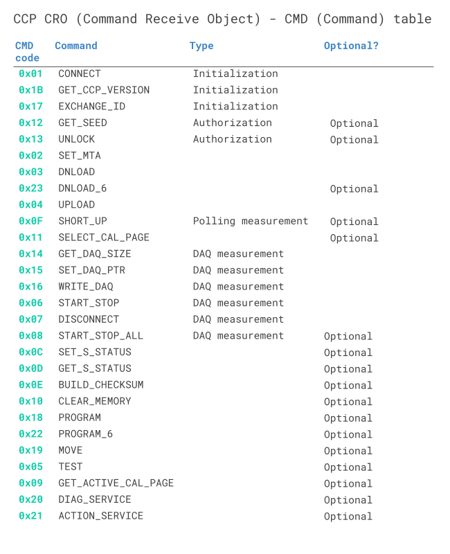
The Command Receive Object (CRO) is a CAN frame sent by the master to an ECU. The 1st byte of the data payload is the command byte (CMD). This controls what command is being issued by the master to the ECU as per the table overview.
To track the commands issued, the 2nd byte is a counter (CTR). It is indented by +1 for every command sent by the master and is mirrored in the response from the slave ECU. The remaining 6 bytes depend on the command.

Example: CCP CRO CONNECT message
Below is an example of a CRO used for initializing communication with a specific ECU:
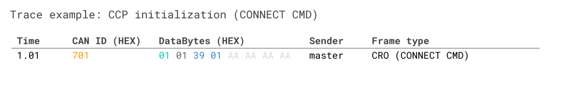
Here, the CAN ID reflects the ID used by the CCP master for communication. The 1st byte is 0x01, corresponding to the CONNECT command as evident from the previous table. The 2nd byte is the CTR value. The 3rd and 4th bytes are specific to the CONNECT command and correspond to the target ECU's station address in Intel byte order. In other words, the above CRO is used by the master to establish a connection with ECU 0x0139. All subsequent communication will in this case be with this specific ECU until the master terminates the connection or connects to another ECU.
DTO - Data Transmission Object
The Data Transmission Object (DTO) is a CAN frame sent by the ECU to the master. Three types of DTOs exist as outlined below:
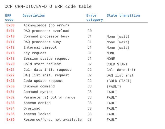
#1 CRM-DTO: Command Response Message
The CRM-DTO is sent by the ECU in response to a CRO from the master. The ID reflects the CAN ID used by the ECU (e.g. 0x702).
The data payload for the CRM can be broken down as follows:
- The 1st byte is the Packet Identifier (PID). For the CRM-DTO, the PID always equals 0xFF
- The 2nd byte is the error code (ERR), which can be used to e.g. inform the master of an invalid request.
- The 3rd byte is the counter (CTR), which will match the CTR value from the master's CRO
- The remaining 5 bytes depend on the CRO request

Note that error codes can be sent in both CRM-DTOs (if they happen in direct response to a CRO from the master) or in EV-DTOs (if they happen asynchronously to the master's CRO commands).
Example: CCP CRO CONNECT message (incl. response CRM)
Below is the previous connection example trace, including a positive response CRM.
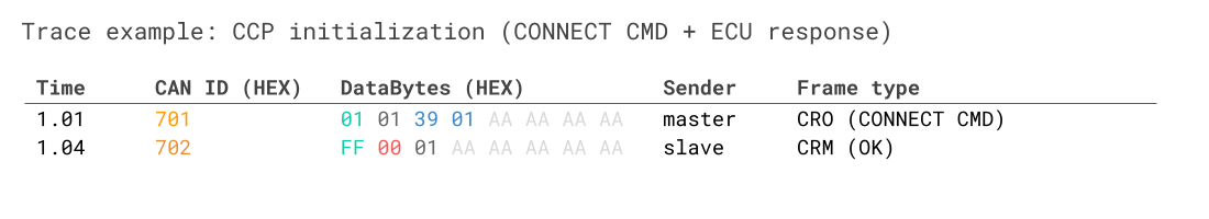
The trace shows a connection to the ECU with station address 0x0139, which responds to the initialization command sent by the master. As evident, the 1st byte is 0xFF (as the message is a CRM). The 2nd byte shows that no errors occurred, while the 3rd byte matches the CTR of the CRO. With this sequence, the connection between the master and ECU 0x0139 is established.
#2 EV-DTO: Event Message
The EV-DTO is sent by the ECU in response to an internal event causing a status change in the ECU. This can be used to inform the master of errors that occurred since the last CRO.
The EV-DTO is identical to the CRM-DTO, but with the PID always equal to 0xFE. Note that the CTR has no relevance for EV-DTOs.

#3 DAQ-DTO: Data Acquisition Message
The DAQ-DTO is used by the ECU to send data to the master in response to an event (e.g. a cyclic counter or button).
In DAQ communication, the master starts out by 'configuring' the ECU for a measurement sequence. Once initiated, the ECU outputs DAQ-DTOs without further CROs from the master.
In the DAQ-DTO the PID refers to an 'Object Descriptor Table' (ODT), while up to 7 bytes carry data related to the ODT.

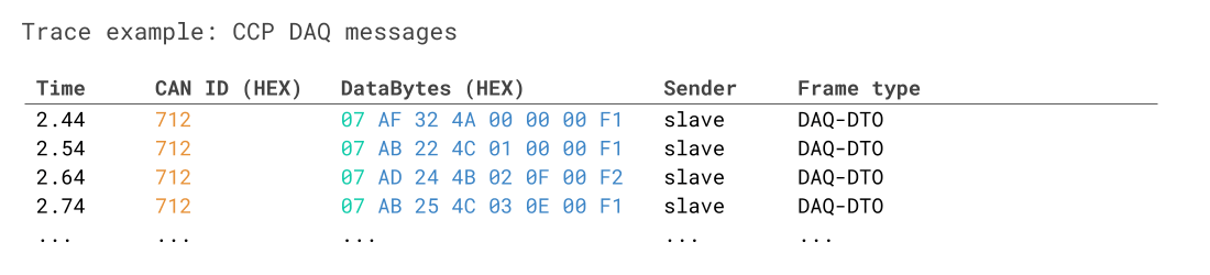
Example: CCP DAQ-DTO
Below is an example of a DAQ-DTO message sent by an ECU to a master.
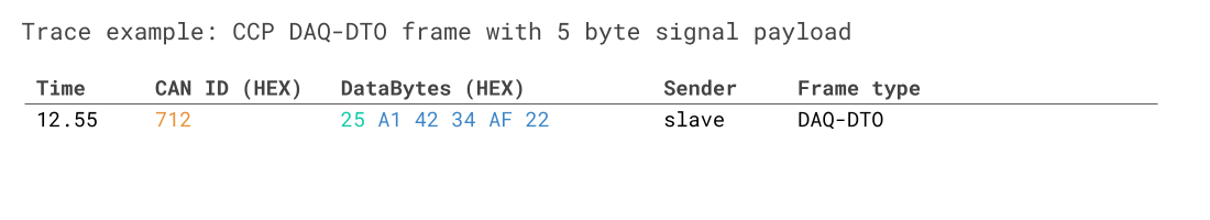
The trace shows the DAQ-DTO communication from a slave following an initial configuration sequence. The data relates to ODT list #37 (0x25) with a payload of 5 bytes. Note how we do not pad the unused bytes (as this is not required for DAQ-DTOs). Note also how a new CAN ID is introduced for this DAQ response (more on this later).
CRO, CRM-DTO and EV-DTO messages must have a payload length of 8. Any unused bytes are padded with arbitrary values (we use 0xAA in this intro). DAQ-DTO messages may use the actual payload size.
Next, we consider XCP on CAN (and compare it to CCP), after which we cover CCP/XCP data logging.
XCP on CAN - the basics
We have now gone through the basics of CCP. In this section, we cover XCP on CAN with focus on message structures.
XCP on CAN - CAN frame identifiers
XCP communication requires at least two CAN bus identifiers: One for the master (e.g. 0x551) and one for the ECU (e.g. 0x552). If the master needs to communicate via XCP with more than one ECU, an additional set of identifiers will be required. This is in contrast to CCP, where ECU addressing is not linked to the CAN ID, but instead set up in the session connection.
XCP CTO - Command Transfer Object
In XCP on CAN, the CTO is a CAN frame for transferring control commands, incl. commands (CMD), command responses (RES), errors (ERR), events (EV) and service requests (SERV).
In contrast to the CRO in CCP, the CTO is used by both the master and ECU. Note also that a CMD packet from the master must be answered with a RES or ERR packet from the ECU, while the other packet types are sent asynchronously.
If we look at the CTO payload, the 1st byte reflects a Packet Identifier (PID). The remaining 7 bytes in an XCP on CAN CTO payload consists of data, specific to the type of CTO packet.
If we compare this structure to the CCP CRO, it is similar, except for the exclusion of the counter byte in XCP.
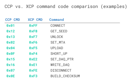
The actual values of the CMD byte across XCP and CCP differ as well. For example, CCP uses 0x01 for the CONNECT command, while XCP uses 0xFF. See also the table overview for the assignment of CTO PIDs depending on whether messages are sent from the master or slave. See also the comparison of CCP vs. XCP CMD codes in the table above.


XCP CONNECT + GET_STATUS response tables
Below we show how to interpret the ECU responses to two core XCP commands.
Example 1: XCP CTO CONNECT message
As in CCP, let's look at how a CONNECT sequence may look in XCP on CAN:
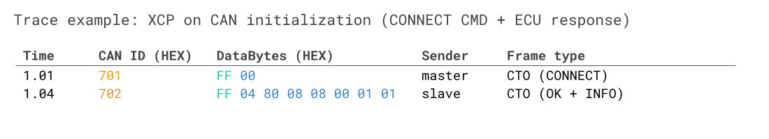
Note that the example does not use the 0xAA padding, as this is optional in XCP on CAN.
In the trace, the master sends a CONNECT CMD (0xFF) to the ECU with the communication mode set to normal (0x00). Note that, in contrast to CCP, the master does not need to specify a station address in the payload of the CONNECT frame. This is because the CAN identifiers already uniquely identify which ECU the master is communicating with.
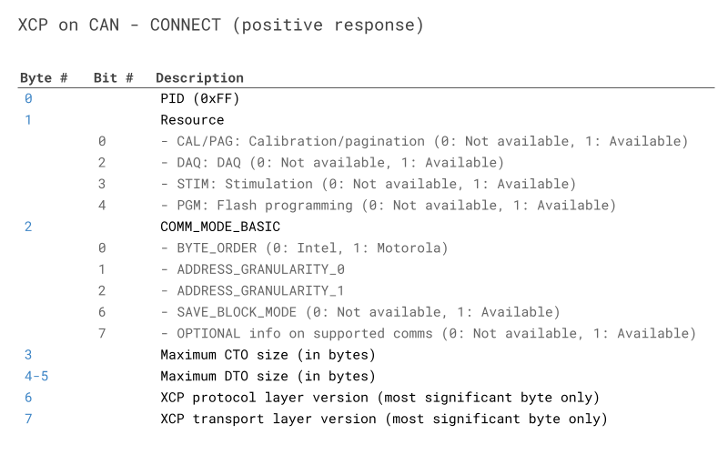
The ECU responds with a CAN frame that can be decoded as per the CONNECT table above:
- The 1st byte equals the positive response PID 0xFF (RES)
- The 2nd byte is the resource availability (0x04 = 0b00000100 means that DAQ is available)
- The 3rd byte relates to the 'communication mode' (0x80 = 0b10000000 e.g. tells us that Intel byte order is used)
- The 4th byte is the maximum CTO size (here 8 bytes, meaning we are limited to Classical CAN CTOs)
- The 5th and 6th byte equal the maximum DTO size (here 8 bytes, meaning we are limited to Classical CAN DTOs)
- the 7th and 8th bytes equal the XCP protocol layer version and transport layer version respectively (both 1 in this case)
Example 2: XCP CTO GET_STATUS message
Below is another example, showing an XCP GET_STATUS request/response:
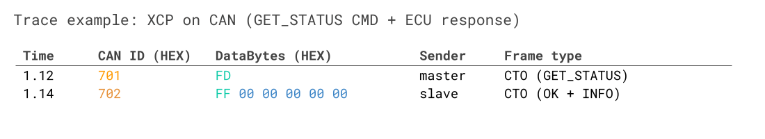
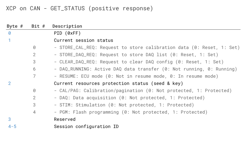
As before, we can interpret the response based on the table:
- The 1st byte equals the positive response PID 0xFF (RES)
- The 2nd byte is the session status (0x00 means that everything is reset and no active DAQs are running)
- The 3rd byte relates to the seed & key protection status (0x00 means that no commands are protected)
- The 5th and 6th byte equal the session config ID (0x00 means no active session)
The GET_STATUS command is particularly useful for obtaining information about whether certain commands (e.g. related to data acquisition via DAQ lists) are protected via seed & key authentication. Note that basic XCP polling via SHORT_UPLOAD commands is never protected via seed & key authentication.
XCP DTO: Data Transfer Object
The XCP DTO is used for sending synchronous data. In particular, the DTO is used in DAQ measurement (similar to the role of the DAQ-DTO in CCP). In XCP, it also enables the transfer of 'stimulation' (STIM) data that can be used in bypassing the normal algorithm within an ECU.


The XCP DTO timestamp
One important thing to note about XCP DAQ measurement, however, is that it enables the ECU to write the measurement time in the XCP DTO packets. The implication is that the master is able to correctly sync ECU data split across multiple frames by utilising the ECU measurement timestamp, rather than the master's own internal timestamp.
The XCP DTO timestamp is optional and is implemented as an incrementing counter, with the incrementation logic specified in the A2L file. If a timestamp is to be included for a specific DAQ list, it will be written into the 1st ODT list (but not subsequent ones if more ODT lists exist within the same DAQ list).
It is also worth noting that multiple methods exist for packing the DAQ list # and ODT list # information in the DAQ DTOs. The simplest case is 'absolute ODT numbers', where the ODT list # is unique across all DAQ lists. Here, the PID (i.e. ODT #) is sufficient for globally identifying an ODT list. In the section on data logging we showcase this in action.
Another method exists, however, where relative ODT list numbers are used across DAQ lists. Thus, you could e.g. have two ODT lists with PID = 0x00, meaning that they cannot be uniquely identified as the CAN ID is identical across the two DTOs. Here, a 1 or 2 byte DAQ list identifier can be added in the 2nd to 3rd bytes of the CAN frame payload. With this, one can again uniquely identify a specific ODT list.
The A2L file and ECU will provide information on what method is used.
A 1-byte counter field may optionally be used in the communication of XCP DTOs. If a CTR field is used in XCP DTO DAQ packets, the slave will only insert the value of the CTR in the 1st frame of a DAQ list, i.e. in the 1st ODT list.
Most of our XCP on CAN overview assumes that the lower layer is Classical CAN. However, since v1.2, XCP can also be based on CAN FD, which adds a number of opportunities for optimization. If an ECU supports XCP on CAN FD, it may support longer CTO/DTO payloads beyond 8 bytes, which will then be evident from the CONNECT response by the ECU as per the table.
Support for CAN FD CTOs enables the master to leverage longer CAN FD frames when initializing DAQ lists, which can reduce the number of separate CAN messages significantly. Further, support fro CAN FD DTOs may allow for encoding much more ECU signal values into the same CAN frame data payload. This is powerful because it reduces busload, but also because it allows for better time synchronization of the data (as will become evident in the data logging section).
CCP/XCP of course contain numerous more topics that we have not taken the time to discuss here. Deliberately, we have focused on the basic topics and concepts related to data logging. However, below you'll find useful links for further reading.
- Vector's XCP Book v1.5: A detailed overview of the XCP 1.5 protocol
- XCP (Wikipedia): The basics on the XCP protocol
- ASAM MCD-1 XCP overview: Also provides a detailed overview of the XCP protocol
- ASAM ASAM MCD-2 MC overview: Provides an overview of the ECU description file standard
- Seed & key details (Vector): A useful intro to the basics on authorization
XCP on CAN vs CCP: Message structure comparison
Below we summarize the structural message differences in XCP on CAN vs. CCP:

An alternative way to illustrate the role of the CCP vs. XCP messages is via below architecture comparison:


How to record ECU data via CCP/XCP
Let us imagine that you are an engineer working at an automotive OEM. You have been tasked to extract the value of a specific parameter from an ECU over an extended period. How do you do it? Below we will outline two methods: Polling and DAQ.
Data acquisition via CCP/XCP polling
The simplest solution is CCP/XCP polling. Here, the master requests data on an ECU signal and the ECU responds with the data. This is done via CRO/CRM-DTO messages (CCP) or CTO messages (XCP). Let us illustrate this method with two examples:
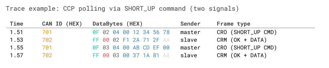
Example 1: CCP polling (CRO/CRM-DTO)
Assuming the CCP master has connected to an ECU, it can poll data as below:
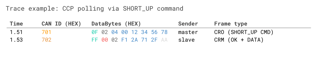
Here, the master sends a request to the slave for 0x04 bytes of data stored at the 'source address' 0x12345678 (Motorola byte order) - corresponding to a specific ECU signal. The 4th byte 0x00 reflects the source address 'extension', which may correspond to a certain memory segment. The slave responds with the current ECU signal value (4 bytes of data, 0xF12A712F).
This can be repeated to e.g. extract real-time parameter data, such as an RPM signal - similarly to how you request RPM via an OBD2 request/response flow in most cars.
Effectively, 'polling' is simply a sequence of CRO/CRM-DTOs with the master using a command called SHORT_UP (short upload).

Example 2: XCP on CAN polling (CTO)
Assuming the XCP master has connected to an ECU, it can poll data as below:
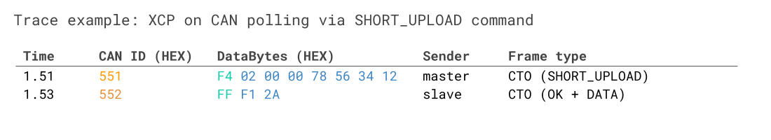
As before, the master sends a SHORT_UPLOAD CMD (PID 0xF4) for 2 bytes of data. The 3rd byte is reserved, while the 4th byte of the CTO is the address extension (in this case 0). The remaining 4 bytes equal the source address 0x12345678 (Intel byte order). In response to the command CTO, the ECU sends a response CTO with the value of the 2 bytes of data.
For CCP/XCP communication, incl. polling, the byte order is ECU specific and described in the A2L file. In the examples above we therefore provide both an Intel and Motorola example, though the selection here is arbitrary and not linked to whether the protocol is CCP or XCP. You can also identify the byte order based on the XCP CONNECT response by interpreting the 3rd byte (communication mode).
One restriction, however, is that in CCP communication the CONNECT message 2-byte station address is always Intel byte order.
Downsides to CCP/XCP polling
Polling is simple to set up - just establish an ECU connection and send the correct request message every X ms. For many practical use cases this can be a perfectly viable solution. However, polling has two significant downsides.
#1 Polling is inefficient
Polling requires a request message for every response. If you e.g. need to measure a 2-byte signal at 100 Hz, that increases the busload by 200 frames/second.
The inefficiency is both due to the need for requesting every single response - but also the fact that response messages are forced to be 8 bytes long, with 3 bytes spent on overhead.

#2 Polling is asynchronous
When polling for multiple signals, the request/responses need to be sent sequentially with a small delay between each request.
As a result, the signal observations are not time synchronized. This makes data analysis more difficult and less precise.
Beyond the above downsides, there can also be more subtle issues with CCP/XCP polling. For example, if your goal is to poll 50 signals with a device that is restricted to sending 1 transmit message per 10 ms (e.g. for safety reasons), the 'cycle period' of each signal would become 50 x 10 ms = 500 ms. In other words, you'd only be able to get a refresh rate of 2 Hz on each signal, which is rarely sufficient for XCP data acquisition purposes.

Data acquisition via CCP/XCP DAQ
CCP/XCP offers an alternative data measurement technique called DAQ (Synchronous Data Acquisition).
How DAQ works + key benefits
DAQ is more complex, but solves the downsides of polling.
The master specifies which ECU signals to record from the slave, what event should trigger the communication of data and how to package the signals. In terms of events, the master may e.g. request that signals A and B are broadcast every 10 ms, while signal C is broadcast every 100 ms - or when a button is pushed.
Once the DAQ configuration is complete, the master 'starts' the sequence and the slave now autonomously broadcasts the requested signals using DAQ-DTO messages.
This eliminates the request messages from the master. In addition, the signal data is packaged more efficiently in the DAQ-DTOs vs. the CCP CRM-DTOs or XCP CTOs, reducing busload.
Further, with DAQ it is possible to package related signals in the same DAQ-DTO frames to enable time synced analysis.
To use DAQ, the master has to first configure the ECU accordingly. Two concepts are key in this regard: Object Descriptor Tables (ODT) and DAQ lists.

Object Descriptor Table
The Object Descriptor Table (ODT) is a list of references to data elements from the ECU memory.
If we take the 'short upload' example used in CCP/XCP polling, the master sends a request specifying three elements: The data length (in bytes), address extension and source address. With this info, the ECU finds the data and sends it to the master.
The concept of an ODT is similar: An ODT is simply a list of 'element references'. Each entry in the ODT reflects an ECU source address (and optionally an address extension and length). The ODT thus describes how ECU signals are 'packaged' in a DAQ-DTO payload.
The master defines ODTs during DAQ initialization - and therefore also knows how to decode the DAQ-DTOs.

Let us consider an example: We wish to record 7 signals, each of them with a length of 1 byte. To do so, we define a new ODT #0 (PID 0x00) with 7 element entries. Element 1 refers to signal 1 with a specific ECU source address. Element 2 refers to signal 2 with another source address etc.
When we use the DAQ mode for data measurement, we can now refer to ODT #0 in order to get the ECU to provide us with time synced data on all 7 signals - within a single DAQ-DTO CAN frame. In other words: The ODT we defined describes the structure of a DAQ-DTO message, meaning that the ECU will now know how to package the 7 signal bytes in a single CAN frame - and the master knows how to extract the 7 signal bytes from that CAN frame.
Notice the impact on the busload: If we were to poll all 7 signals, it would require 14 CRO/CRM-DTO CAN frames per cycle - now it only requires 1 DAQ-DTO CAN frame. Further, we can easily plot these 7 signals together as they share the same CAN frame timestamp - making it much easier to perform analysis. For the same reason, ODT lists are typically defined to group related signals together.
In practice, a master will often define multiple ODT lists and assign PIDs for each of them in the range of 0x00 to 0xFD. Each ODT then defines the structure of a separate DAQ-DTO.
DAQ lists
When working with multiple ODTs, it is useful to group them based on sampling method (e.g. every 10 ms, 100 ms, on-event). These groups of ODTs are referred to as DAQ lists. DAQ list #0 may e.g. contain ODT #0, ODT #1 and ODT #2. The ECU A2L file specifies the supported DAQ lists (aka events) and which signals/measurements can be assigned to each event type.

How to initialize a DAQ sequence
We have now looked at both the ODT and DAQ lists - but how do we define these over CAN?
In simple terms, the configuration of DAQ lists is done through a (potentially long) sequence of CCP CRO/CRM-DTO or XCP CTO frames. Here, the master essentially specifies the entire DAQ/ODT/element structure element-by-element. To define a new signal (aka element), the master specifies the address, length and address extension. Next, the master informs informs the ECU how to package the element in DAQ-DTOs by linking the element to an ODT# and DAQ#.
To understand this in detail, consider below trace examples/explanations:
Example 1: CCP DAQ - initialization
The below shows a basic CCP DAQ initialization sequence.
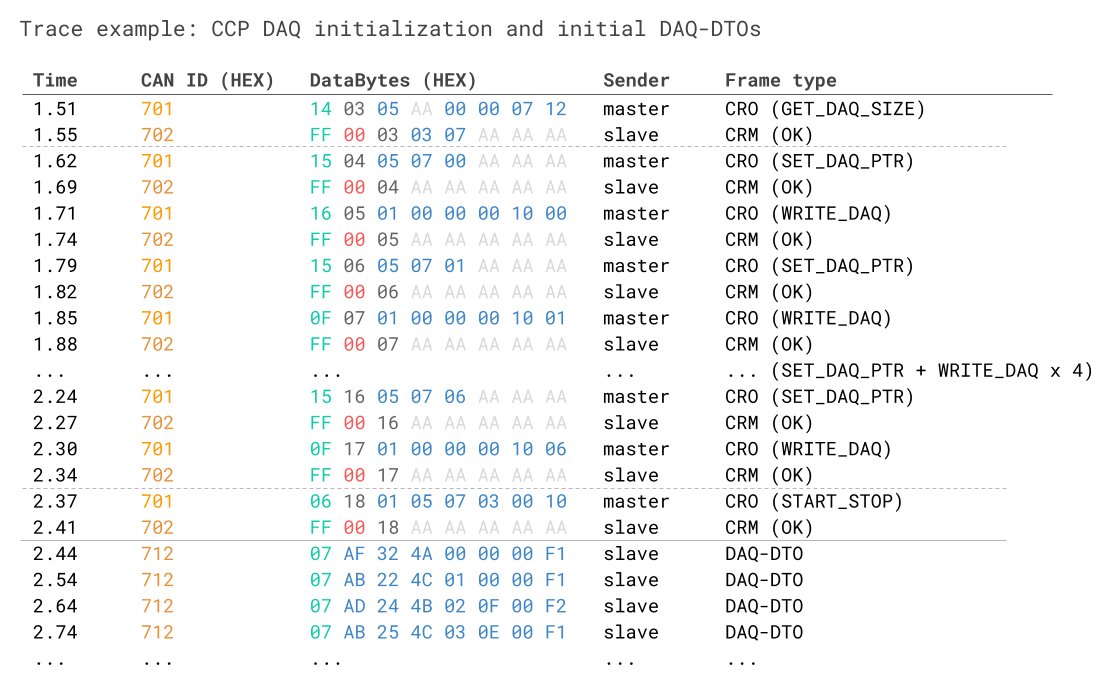
So we have quite a bit going on here, but let's break it down:
We start by using the CRO command GET_DAQ_SIZE. This has two purposes: It informs us about the size of the specified DAQ list in terms of ODT lists - and it clears the current list. Essentially, this works like a 'reset' command for the DAQ list, in this case DAQ list #5.
As part of the GET_DAQ_SIZE command we also provide the 11-bit CAN ID 0x712 in the last 4 bytes. This informs the ECU that it should use CAN ID 0x712 to broadcast the subsequent DAQ-DTOs. This is subtle, but an important aspect: Essentially, the master is able to specify the CAN ID for every DAQ list, which in turn also enables the master to initiate DAQ measurement across multiple ECUs in parallel.
The ECU confirms the CRO from the master and informs us that the DAQ list #5 has 3 ODTs with the first PID being 0x07.
Next, the master starts populating DAQ list #5 and ODT list #7 with the source address information for 7 x 1-byte signals. This is done through a simple loop consisting of 7 repetitions of two commands: SET_DAQ_PTR and WRITE_DAQ.
First, the master uses SET_DAQ_PTR to "select" DAQ list #5, ODT list #7 and element #0 of the ODT list. Next, the master uses WRITE_DAQ to write the contents of this element reference: A length of 1, an address extension of 0 and a source address of 0x00001000.
Basically, we have now told the ECU to "package" the value of our 1st signal (which is stored in the specified source address) into the 2nd byte of the DAQ-DTO that corresponds to DAQ list #5 and ODT list #7 (the 1st byte of the DAQ-DTO being the PID 0x07).
After this, we repeat the process for the remaining 6 signals until the ODT #7 has been completed.
In this simplistic case we only care about this particular DAQ and ODT list. Therefore, the final step is to start the DAQ measurement via the START_STOP command. Here, we specify that we wish to start DAQ list #5 and ODT list #7. As part of this, we specify the timing parameters, namely that event channel 0x03 should be used with a prescaler of 10. The ECU specific event channel details are specified in the ECU description file.
As evident, the ECU will now start broadcasting data from DAQ list #5 and ODT list #7 at the specified frequency. The CAN frame payloads include the ODT PID 0x05 in the 1st byte and the 7 'element' signal values in the remaining payload.
Note also that you can alternatively use the START_STOP command to 'prepare' multiple DAQ lists and ODT lists for measurement and then use the START_STOP_ALL command to simultaneously start or stop all of them.
Below example trace shows an already initiated DAQ sequence:
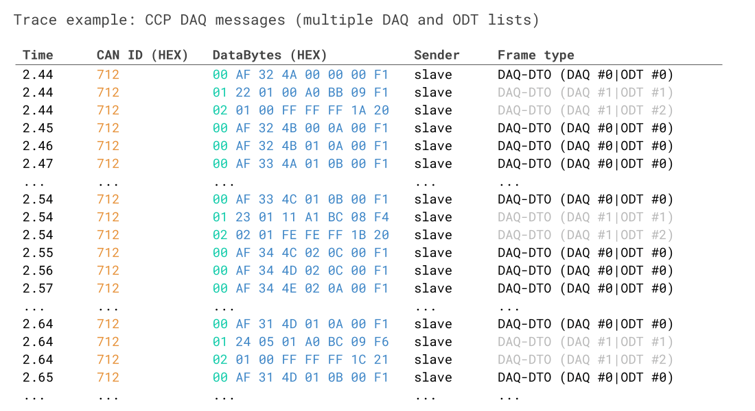
In this example, the target ECU is broadcasting data across three ODTs in total, as evident from the 1st bytes spanning from 0x00 to 0x02. While it's not explicitly clear from the trace, the three ODTs are split into two DAQ lists: One DAQ list contains ODT #0 with a sampling frequency of 10 ms - while DAQ list #1 contains the remaining ODT lists #1 to #2 with a sampling frequency of 100 ms. This is why the DAQ-DTO with PID 0x00 is observed more frequently in the trace vs. the other DAQ-DTOs.
Example 2: XCP on CAN DAQ - initialization (Classical CAN CTOs/DTOs)
The below shows a basic XCP on CAN DAQ initialization sequence for 1 DAQ list and 4 ODTs. The master uses Classical CAN frames for both the initialization and the subsequent DAQ-DTOs that carry the ECU signal data.
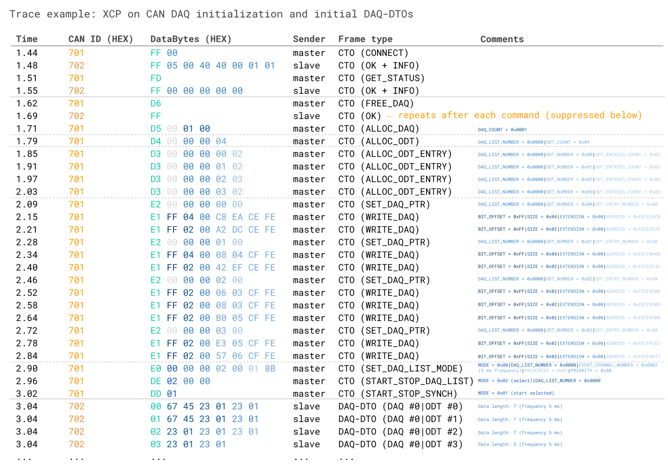
In this trace, we explicitly show the initial CONNECT and GET_STATUS command, which are typically used prior to starting a DAQ initialization sequence. The ECU responses to these commands can yield useful information about DAQ-related capabilities of the ECU as explained in the XCP CTO section - see also the related 'response tables' for these commands. In particular, note that the CONNECT response tells us that the client supports 0x40 (64) byte CTOs and DTOs, though for exposition we use Classical CAN frames in this example only. The CONNECT response also informs us that the ECU uses Intel byte order. The GET_STATUS response tells us that the ECU does not use seed & key authentication for any commands, including DAQ.
Let us outline the rest of the example:
- The master starts by clearing any dynamic DAQ lists via the FREE_DAQ command
- Next, the master uses ALLOC_DAQ to allocate a single DAQ list
- Next, the master uses ALLOC_ODT to allocate 4 ODTs to the DAQ list 0x0000
- After this the master uses ALLOC_ODT_ENTRY for each of the 4 ODTs to specify the number of elements/signals
- Now that the basic allocations are done, the master uses SET_DAQ_PTR to target a specific DAQ list (0x0000) and ODT (0x00). Subsequently the master uses WRITE_DAQ commands to allocate specific ECU signals to the target. Notice how each WRITE_DAQ specifies the byte length of the signal, but not the payload position (this is handled by the ECU). Note also that with Classical CAN, the payload per ODT is limited to 7 data bytes. This process is repeated for each of the 4 ODTs
- Once the signal writing is done, the master uses SET_DAQ_LIST_MODE to 'configure' the targeted DAQ list 0x0000. The 2nd byte, MODE, is set to 0x00, which means the 'direction' is slave-to-master (for data acquisition), timestamps are not included in the DAQ-DTO payloads - and the ODT PID is not disabled, meaning that the 1st byte of the DAQ-DTOs will reflect the ODT identifier field. The EVENT_CHANNEL_NUMBER 0x0002 is linked to a specific 'trigger event' in the ECU, in this case implying that the DAQ list is broadcast periodically every 5 ms. The prescaler value is set to 1, meaning we do not downscale the frequency of the DAQ list
- Finally, the master uses the START_STOP_DAQ_LITS to 'select' DAQ list 0x0000 for synced startup - and then uses START_STOP_SYNCH to actually trigger the start of the DAQ-DTO communication from the ECU
At the end of the trace we see how the ECU starts producing the four separate DAQ-DTOs, each linked to the relevant ODT via the PID in the 1st byte. Note also how the length of the DAQ-DTOs corresponds to the total byte length of the signals assigned to the respective ODTs during the WRITE_DAQ step.
Example 3: XCP on CAN DAQ - initialization (multiple DAQ lists + CAN FD DTOs)
The below shows a more advanced XCP on CAN DAQ initialization sequence using Classical CAN frames for the initialization of 2 DAQ lists carrying a total of 3 ODTs. Notice how one of the DAQ-DTOs is a CAN FD frame with 32 bytes.
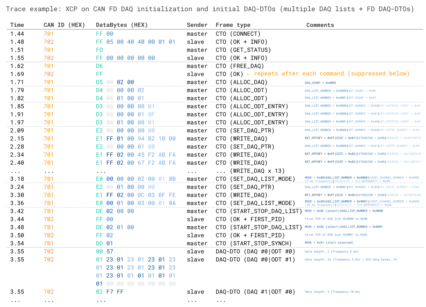
This trace is very similar to the previous one, but now includes multiple separate DAQ lists. A few highlights:
- In DAQ list 0x0000 ODT 0x01 the master assigns 0x0F (15) elements, which requires 15 x WRITE_DAQ commands because the master uses Classical CAN frames for the initialization. The total byte length of these 15 elements is 24 bytes as evident from the final DAQ-DTO related to this ODT. When accounting for the PID, that means 25 bytes are required in total. In CAN FD, it is necessary to 'round up' to the closest supported data length, which in this case is 32 bytes - meaning that some padding is included
- Notice also how we include the ECU slave responses to the two START_STOP_DAQ_LIST commands. This is to show how the ECU responds with the FIRST_PID value, telling the master what the first PID is for each DAQ list (related to absolute PID numbering)
- The example also shows how the two DAQ lists use separate event channels (0x0002 = 5 ms and 0x0003 = 10 ms periodic broadcast)
Example 4: XCP on CAN DAQ - initialization (CAN FD CTOs via WRITE_MULTIPLE_DAQ + CAN FD DTOs)
This example leverages the XCP command 'WRITE_MULTIPLE_DAQ' to write 7 signals in a single CAN FD frame - thus reducing initialization time and overhead. The DAQ-DTO also leverages CAN FD to pack the 7 signals (14 data bytes) in a single frame.
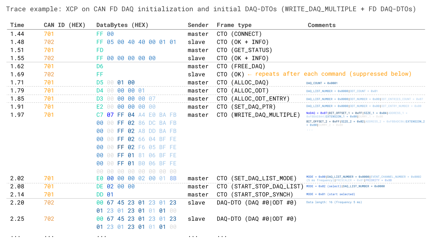
In this example, the master fully leverages CAN FD in both the XCP CTOs (for the initialization) and DTOs (for the subsequent DAQ-DTO communication).
Specifically, the master uses the WRITE_DAQ_MULTIPLE to add 7 elements to a single DAQ list and ODT within a single write command. As evident, this command requires specifying the number of elements (0x07) and then essentially parsing a similar structure as in the regular WRITE_DAQ commands, though with the extension and ECU address field order reversed.
The resulting DAQ-DTO contains all 7 elements (14 data bytes). As the required data length incl. the PID is 14 + 1 = 15 bytes, the closest CAN FD frame length is 16 bytes and therefore 1 byte of padding is added.
How to disconnect from an ECU
Once the data acquisition has completed, the master may disconnect from the ECU via the DISCONNECT command.
Example 1: CCP DISCONNECT
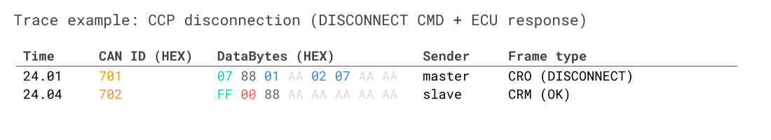
Here, the 3rd byte 0x01 means that we end the session entirely (in contrast to a temporary disconnection). This effectively resets the ECU including our previous configuration. To target the specific ECU of interest, we specify the station address (Intel format) of the ECU, i.e. 0x702.
As evident, DAQ is more convoluted to set up - but enables efficient time synced communication of ECU data.
Example 2: XCP on CAN - stop DAQ + DISCONNECT
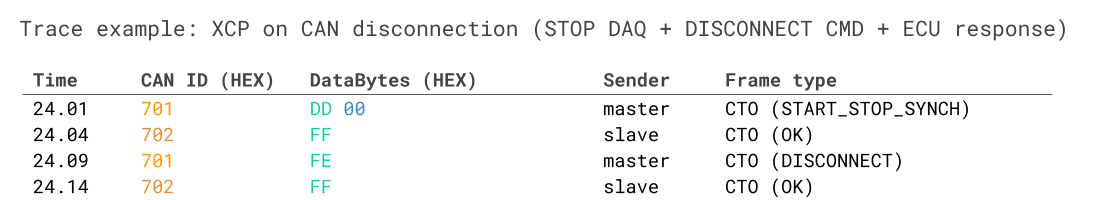
In this example, the master first stops the existing DAQ communication via the START_STOP_SYNCH command (with the 2nd byte set to 0x00). After this, the master disconnects the overall XCP session. Notice how this command is simpler vs. CCP as the XCP master does not need to target a specific ECU address (as this is implicit from the CAN IDs used).
1: Decoding CCP/XCP signal data from ECUs
In CCP/XCP polling/DAQ, you are in practice recording raw CAN frames with specific signal encoding structures.
In order to make sense of the recorded data, you need to decode it to human-readable form aka physical values. This is the same concept as we've explained in several other CAN-related intros, incl. our intro to CAN bus, J1939, OBD2 and DBC files.
However, CCP/XCP decoding involves some extra complexities that we will explain below.
2: Decoding CCP/XCP polling data
Let us review an extended version of the CCP polling request/response from before:
This reflects a decoding challenge: The ECU sends different signals with the same CAN ID - with no way to identify them in the payload.
In the above example, the master is requesting two different 4-byte signal values from the ECU, namely from source addresses 0x12345678 and 0xABCDEF00. In both cases, the ECU responds with CAN ID 0x702.
In most CAN bus decoding scenarios, you would be able to simply lookup the response CAN ID and find the 'start bit' and 'bit length' of a given signal to extract the raw data from the payload.
However, that is not possible here as the ECU uses the same CAN ID across two different signals. In other words, the CAN ID is not sufficient to distinguish between the signal coming from 0x12345678 and the one coming from 0xABCDEF00.
To some extent, this is similar to how OBD2 responses from an ECU use the same CAN ID (typically 0x7E8) across different signals like speed and RPM. In the case of OBD2 we can, however, easily solve this because the OBD2 PID (Parameter Identifier) is included in the payload. Together with the CAN ID, this serves as a unique identifier within the response frame - enabling us to view the response as a case of multiplexing.
We cannot directly do this in CCP polling because the response payload does not include the ECU source address. In other words: In use cases with multiple CCP polling signals we need to combine information from the request & response message.
In simplistic terms, we can solve this by "repackaging" the payloads as follows:
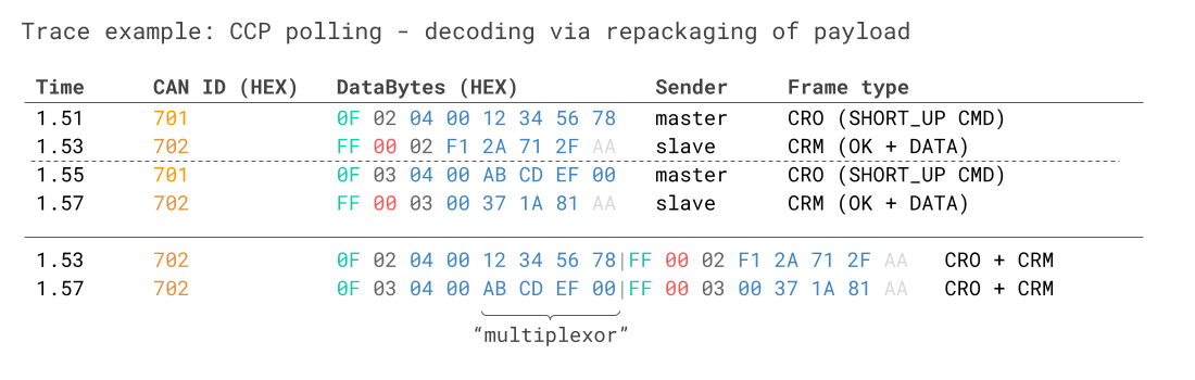
By doing so, we can process this using multiplexing logic - similar to how we handle OBD2 and UDS decoding. Here, the CAN ID to look up is 0x702 and the multiplexor is found in the 5th to 8th byte, while the signal value is found in the 12th to 15th byte. Two separate decoding rules can now be specified, with the relevant one dependent on the value of the 4-byte multiplexor.
In practice such a reconstruction of CAN frames can be done in e.g. a Python script, assuming the CAN trace includes both the request and response data. Once the CAN frames are reconstructed, it is possible to use DBC files for decoding the data via multiplexing. Alternatively, the data can be loaded into a software tool supporting CCP/XCP decoding directly.
Decoding CCP/XCP DAQ data
Let's briefly review a snippet of the post-initialization DAQ trace from before:
As evident, the DAQ-DTO messages have a pre-specified CAN identifier (0x712 above) and a payload in which the 1st byte equals the ODT list identifier aka ODT PID (0x07 above). As a result, it is not necessary to "combine" the DAQ-DTO response frames to uniquely identify which frames contain which signals - this can directly be identified through a combination of the CAN ID and the ODT PID.
This fact makes the decoding of DAQ-DTO messages simpler than the polling messages. In fact, you can directly create a DBC file with multiplexing as long as you know the signal encoding in the remaining bytes of each ODT list.
In most practical applications, it is reasonable to assume that you will know this signal encoding. This is because the master itself controls (via the initialization sequence) how to package each signal into the DAQ and ODT lists, as explained in the previous section.
For example, we know that the DAQ-DTOs with CAN ID 0x712 and ODT PID 0x07 contain the signal with source address 0x00001000 in the 2nd byte - because that is how we packaged it during the initialization. From the ECU description file we can then review how to interpret this 1-byte signal value. The description may state that this signal is a temperature measured in degC and it should be multiplied by a factor of 0.8 and offset by 20. If you're familiar with DBC files, you'll note that such information can easily be entered into a DBC, allowing for quick decoding of the trace data in most CAN software tools.
Naturally, if the master changes the initialization to package the data differently on another test run, the implication will be that the DBC file must be updated accordingly.
The above should make it clear that CCP polling/DAQ can be treated within the normal logic of CAN bus frame decoding - though both involve some tweaks. DBC files can be used to process the data - but this format is not the most common choice for working with CCP data. Below we explore another file format that is generally used, the A2L or ASAP2 format.
A2L - ECU Description Files
In the prior sections, we've occasionally referred to "ECU description files". An ECU description file contains everything a master tool needs to know to communicate with an ECU. From a data measurement perspective, this includes information on CAN identifiers, available signals, signal decoding rules, DAQ/ODT information etc.
In practice, the ASAP2 description format (*.A2L) is used to structure this information. The ASAP2 data definition was standardized by ASAM in the ASAM MCD-2 MC, with the first version 1.3.1 being released June 15 1999, i.e. the same year that the CCP 2.1 standard was released. The latest version of the standard, 1.7.0, was released in 2015.
You can view an example A2L file here.

In practice, the A2L file is used to "configure" the master device, enabling communication with the ECU. For example, in our previous examples we used the CAN IDs 0x701 and 0x702 for the CRO/DTO communication between the master and ECU. These IDs would be specified in the A2L file.
The A2L also describes how signals are stored in the ECU and how to decode them. See e.g. below snippet from the A2L example file:

As before, we can compare this to the logic of signal encoding in other CAN protocols and in DBC files. The 'MEASUREMENT' tag is used to envelop the description of a measurement signal, in this case Airflow. It has a detailed description and a min/max defined by the lower/upper limit.
The signal also has a 4-byte source address, 0x40000144. If we recall the CCP polling outline, this source address could be used in a SHORT_UP command polling sequence to request the raw value for this particular ECU signal. Similarly, in the context of DAQ measurement, this source address would be used in the initialization process. In other words, an engineer can lookup the signal of interest (Airflow) in a A2L file or A2L GUI tool - and configure his master tool to request this.
Assuming we've now recorded a trace of raw values, we'd need to decode the information. As explained before, the first step would be to extract the raw bytes from the response payload - and the method for doing this will depend on whether we're using polling or DAQ measurement. Further, the byte ordering is not specified by the CCP protocol - but will be specified within the A2L file at a global or signal level.
Once we've extracted the signal bytes and converted them to decimal form, we need to know how to convert them.
In the DBC file context, this would always be done in the form of a 'linear' equation as below:
Here, a equals a scale factor and b equals an offset - both specified in the DBC file for each signal.
In contrast to DBC files, the A2L files allow for more complex conversion methods. As evident from the signal description, it refers to a conversion rule defined as "CompuMethod_6". We can look this up in another section of the A2L file:

As outlined, this conversion rule uses a conversion type called RAT_FUNC. This is one of multiple supported conversion types and is defined as below:
As evident, the rational function is a more sophisticated version of the linear function used in DBC files. In particular, it supports 6 coefficients, which are specified in the computation method. Importantly, the equation is reversed in comparison with e.g. the LINEAR computation method. To compare this to e.g. DBC files, we first need to 'solve for phys'.
In 99% of RAT_FUNC cases, the coefficients a, d, e equal 0, meaning the function can be simplified as below:
In the example, the coefficients are set to 0 1 0 0 0 1, meaning the function simplifies to below:
In this simple case, the rational function simplifies to a linear function, similar to the one used in DBC files. A2L files in fact also support another conversion type, LINEAR, which is simply phys = a*raw + b. In the case of the Airflow signal, this could have been used instead.
Finally, the unit is also specified in the measurement details, meaning we can now plot the Airflow physical value as measured in kg/s. The Format field is %6.2, which should be read as %Length.Layout, with Length reflecting the overall length of the decoded signal and Layout reflecting the number of decimal places.
As is probably clear, one does not normally look through the A2L file via a text editor. Rather, the A2L file is simply loaded in a compatible tool (e.g. a PC GUI tool with a connected CAN interface, or a CAN data logger). This then allows the engineer to use the tool to perform the relevant measurement from the ECU without having to understand the A2L file structure and syntax.
This particular signal is simplistic enough to be described within the restrictive DBC file format - but A2L files clearly allow for more complex decoding rules. For more details on A2L file format, see the ASAM MCD-2 MC standard, as well as a practical overview.
Seed & key authorization
As explained previously, CCP/XCP communication is typically used by automotive OEM engineers to facilitate communication with ECUs in pre-production applications.
In some cases all it takes to communicate with an ECU is the A2L file and a suitable CAN tool. As evident, one can also simply extract a subset of the A2L file to configure a device e.g. for measurement of specific signals. However, without the A2L file, it is practically impossible to perform communication and hence many OEMs do not require any additional security measures beyond keeping the A2L file under lock.
However, some use cases warrant additional security.

CCP/XCP supports this via a concept called 'seed & key' authorization. Here, the master requests a random seed from the ECU as part of the initialization of the ECU communication. The master receives the seed from the ECU and uses it as input for an internal security algorithm to calculate a key. The master then sends the key to the ECU via CAN - and if it matches the key calculated internally by the ECU, authorization is provided for further communication.
Example: CCP seed & key authentication
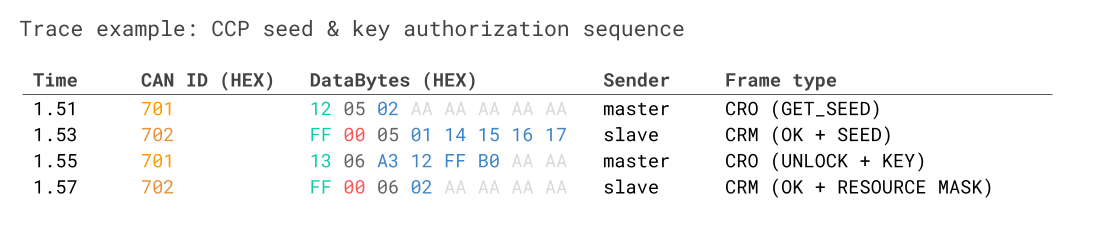
In this example, the master requests the seed via the GET_SEED command 0x12, specifying a 'resource mask' of 0x02 in the 3rd byte. The resource mask references the level of access requested - with 0x02 being DAQ access only (see the CCP 2.1 standard for details).
The ECU responds with a frame in which the 4th byte is 0x01, implying that DAQ access is protected (in contrast to 0x00 which would imply that authentication would not be required). The ECU provides the requested seed in the remaining 4 bytes.
Based on the seed, the ECU calculates the key and provides it via the UNLOCK command, 0x13. The key is in this case 4 bytes long. The ECU responds positively including the requested resource mask 0x02, meaning that DAQ access is now unlocked.
The most common implementation of the security algorithm is via a *.dll file, since the master device is frequently a Windows PC with a GUI tool and a CAN interface. The use of a *.dll file also enables standardization across CCP tools, while eliminating the need for the master tool to know the underlying algorithm used.
It is, however, challenging to use *.dll files in standalone CAN bus data loggers and telematics devices (as they do not run Windows), hence some companies use alternative solutions - e.g. proprietary file formats better suited for embedded devices.
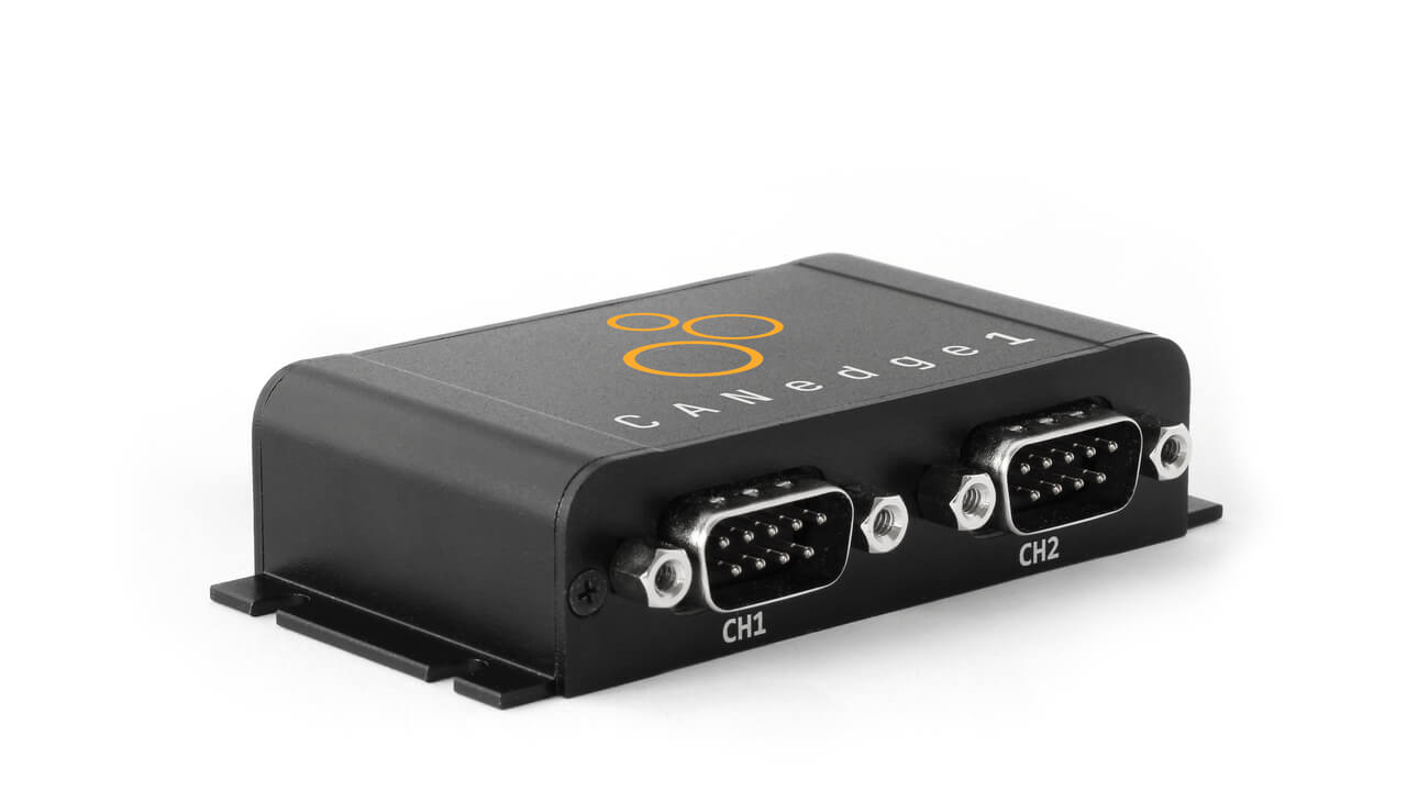
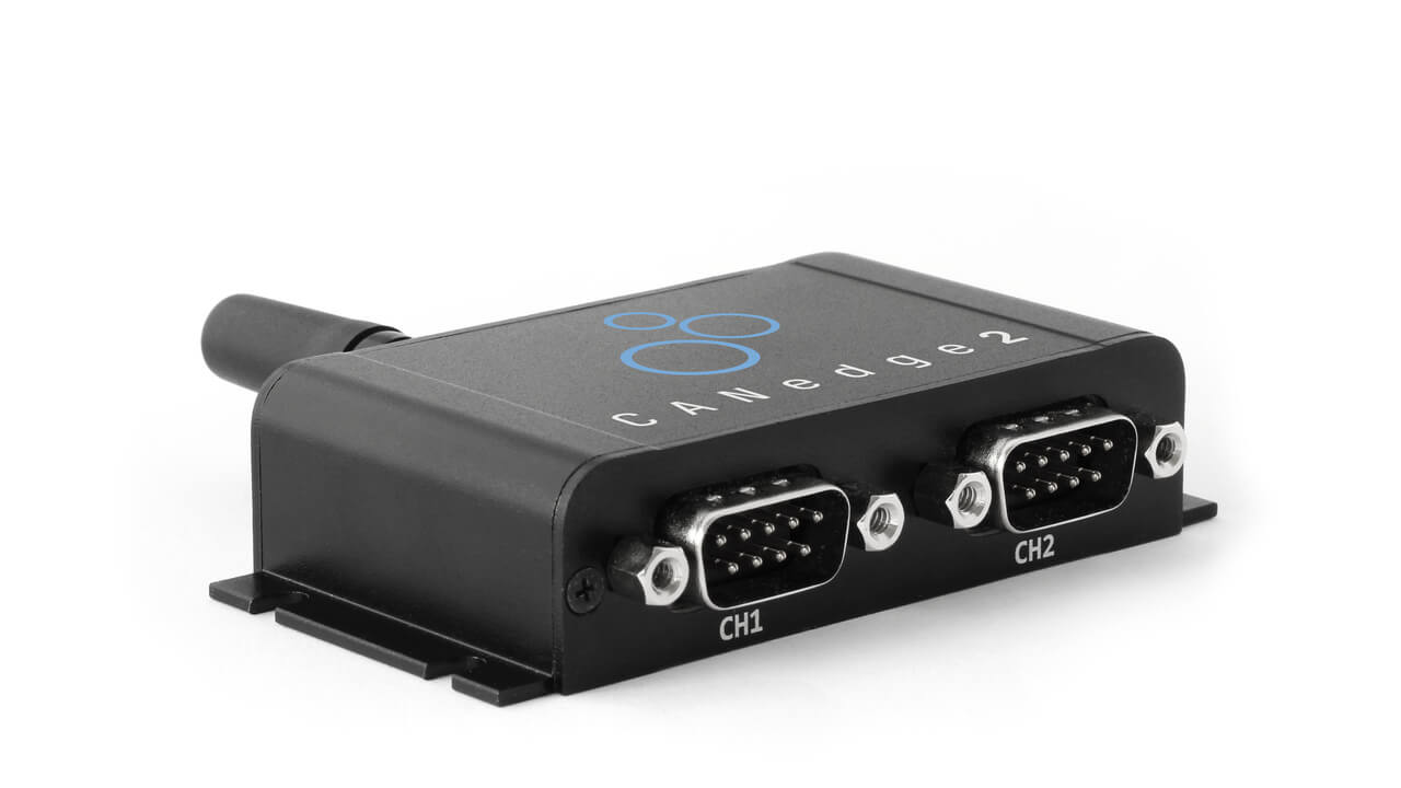
Using the CANedge for CCP/XCP data acquisition
The CANedge is a series of low cost, compact 2 x CAN/LIN bus data loggers. The CANedge is commonly used by automotive OEMs - and for this reason a frequently asked question is whether the device supports CCP/XCP on CAN communication.
As we've seen in the previous sections, all it takes to facilitate CCP/XCP polling and CCP/XCP DAQ measurement is to be able to transmit a specific sequence of CAN frames, based on information that can be identified from an A2L file.
As long as you know how to construct the request frames, you can use the CANedge transmit functionality to set up a list of single-shot or periodic custom CAN frames to e.g. achieve the CCP/XCP initialization and CCP/XCP polling/DAQ measurement. The recorded MF4 log files with measurement data can then be processed in e.g. Vector tools or via our free open source software solutions. In the former case, you could e.g. use our MF4 converters to get the data into Vector tools and use A2L files for decoding the data. In the latter case, you could process the data via our Python API (for polling) and/or via asammdf. These tools require creating a DBC file with the decoding rules as explained previously.
In other words, you can use the CANedge to measure signal data via CCP/XCP on CAN in standalone field deployments, which offers a low cost method for collecting this information at scale.
In contrast, standalone CAN bus data loggers are not ideally suited for CCP/XCP calibration, except for very specific use cases such as remote calibration of variables via over-the-air updates.
The CANedge does not support seed & key authentication - though this is not necessarily an issue in regards to data acquisition.
As evident from the XCP GET_STATUS command, authentication may apply to calibration/pagination, DAQ, stimulation and programming commands. However, authentication is not required for basic commands like e.g. CONNECT, GET_STATUS and SHORT_UPLOAD. If your goal is to perform data acquisition wtih the CANedge, you can use the GET_STATUS command to determine if DAQ is an option or not. If it is not, you can 'fall back' to using CCP/XCP polling.
Further, if you prefer to use DAQ rather than polling, it may also be possible for your team to simply disable authentication for DAQ in the ECU for the purpose of your data logging use case.
CCP/XCP data logging - applications
In this section we provide brief examples of how CCP/XCP data logging may be useful in practice.
CCP/XCP telematics for prototype vehicle fleet
As an OEM, you may need to collect e.g. CAN, CAN FD or LIN bus data from prototype vehicles in the field. In addition, you may need to collect specific data internal to an ECU, which can only be measured via CCP or XCP on CAN. Here, a CAN logger like the CANedge can be configured with a custom 'transmit list' consisting of single shot and/or periodic CAN frames. When deployed in the vehicle, the CANedge will then automatically transmit the pre-defined frames, allowing it to e.g. perform CCP/XCP polling of ECU data - or initialize DAQ measurement. The collected CCP/XCP data can be combined with the general CAN data in MF4 log files - and sent via WiFi/3G/4G to the OEM's own cloud server.


Remote CCP/XCP calibration via OTA updates
As a more sophisticated use case, an OEM could utilize a CANedge3 to perform over-the-air updates to an ECU. For example, a CANedge3 may be deployed in a prototype vehicle in which an OEM engineer would like to re-calibrate certain variables in the ECU. To achieve this, the engineer constructs the relevant sequence of single-shot CAN frames in a new configuration file for the CANedge. Next, the engineer deploys the new configuration file on the CANedge S3 server, thus triggering an OTA update - allowing the CANedge3 to transmit the sequence into the vehicle remotely.
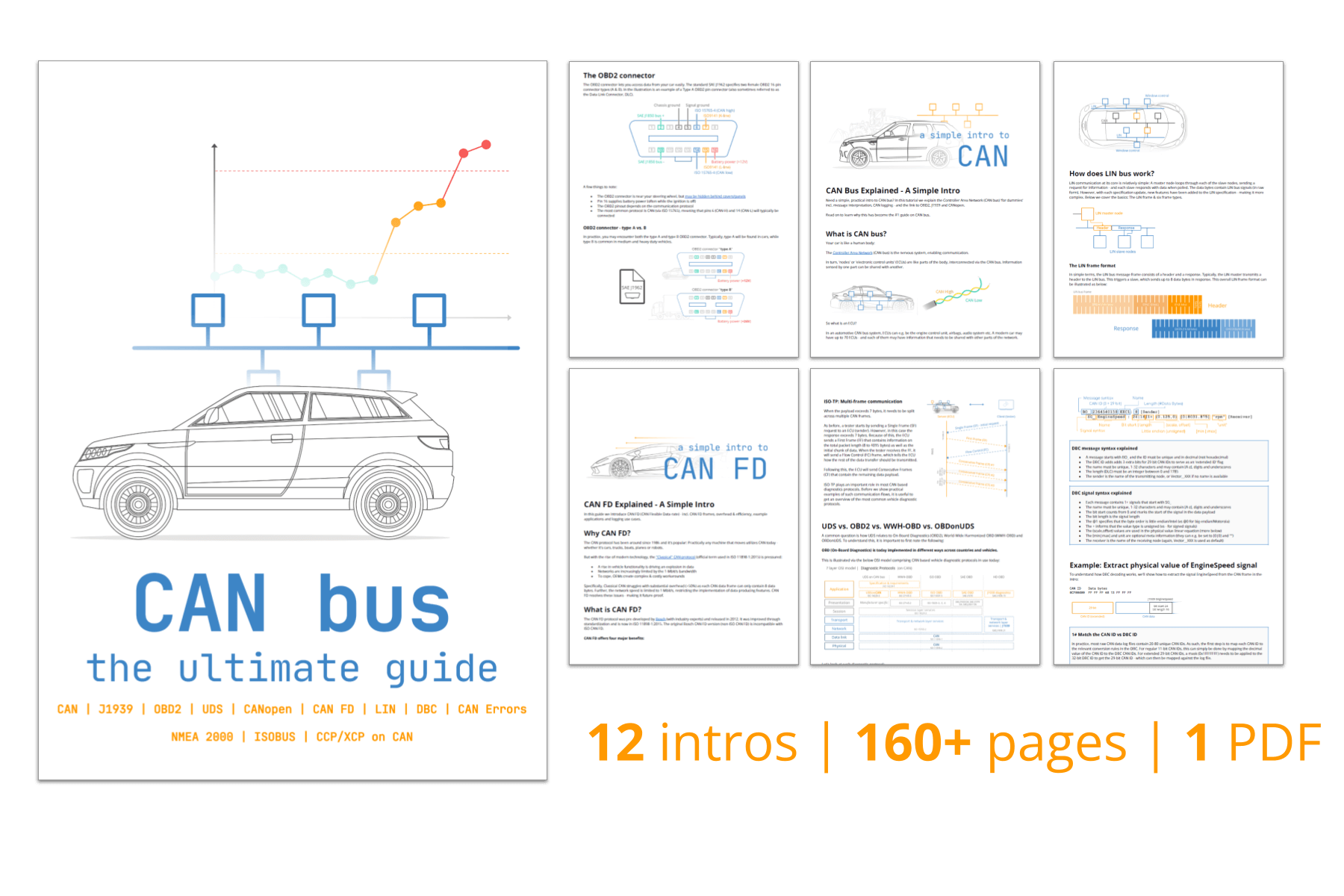
For more intros, see our guides section - or download the 'Ultimate Guide' PDF.
Ready to log your CCP/XCP data?
Get your CANedge today!