LIN Bus Explained - A Simple Intro [2025]
Need a simple intro to LIN bus?
In this guide we introduce the Local Interconnect Network (LIN) protocol basics incl. LIN bus vs. CAN bus, the physical layer, the LIN message frame and frame types, the transport layer (incl. diagnostics) and the LIN Description File (LDF).
Note: This is a practical intro so we will also look at the basics of LIN bus data logging.
Learn more below!
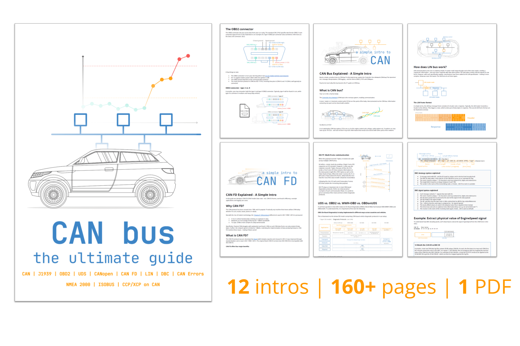
You can also watch our LIN bus intro video above - or get the PDF.
In this article
What is LIN bus?
LIN bus is a supplement to CAN bus.
It offers lower performance and reliability - but also drastically lower costs. Below we provide a quick overview of LIN bus and a comparison of LIN bus vs. CAN bus.
- Low cost option (if speed/fault tolerance are not critical)
- Often used in vehicles for windows, wipers, air condition etc..
- LIN clusters consist of 1 master and up to 15 slave nodes
- Single wire (+ground) with 1-20 kbit/s at max 40 m bus length
- Time triggered scheduling with guaranteed latency time
- Variable data length (2, 4, 8 bytes)
- LIN supports error detection, checksums & configuration
- Operating voltage of 12V / 24V
- Physical layer based on ISO 9141 (K-line)
- Sleep mode & wakeup support
- Most newer vehicles have 10+ LIN nodes


LIN bus vs CAN bus
- LIN is lower cost (less harness, no license fee, cheap nodes)
- CAN uses twisted dual wires 5V vs LIN single wire 12V/24V
- A LIN master typically serves as gateway to the CAN bus
- LIN is deterministic, not event driven (i.e. no bus arbitration)
- LIN clusters have a single master controlling communication
- CAN uses 11 or 29 bit identifiers vs 6 bit identifiers in LIN
- CAN offers up to 1 Mbit/s vs. LIN at max 20 kbit/s
LIN bus history
Below we briefly recap the history of the LIN protocol:
- 1999: LIN 1.0 released by the LIN Consortium (BMW, VW, Audi, Volvo, Mercedes-Benz, Volcano Automotive & Motorola)
- 2000: The LIN protocol was updated (LIN 1.1, LIN 1.2)
- 2002: LIN 1.3 released, mainly changing the physical layer
- 2003: LIN 2.0 released, adding major changes (widely used)
- 2006: LIN 2.1 specification released
- 2010: LIN 2.2A released, now widely implemented versions
- 2010-12: SAE standardized LIN as SAE J2602, based on LIN 2.0
- 2016: CAN in Automation standardized LIN (ISO 17987:2016)

LIN bus future
The LIN protocol serves an increasingly important role in providing low cost feature expansion in modern vehicles.
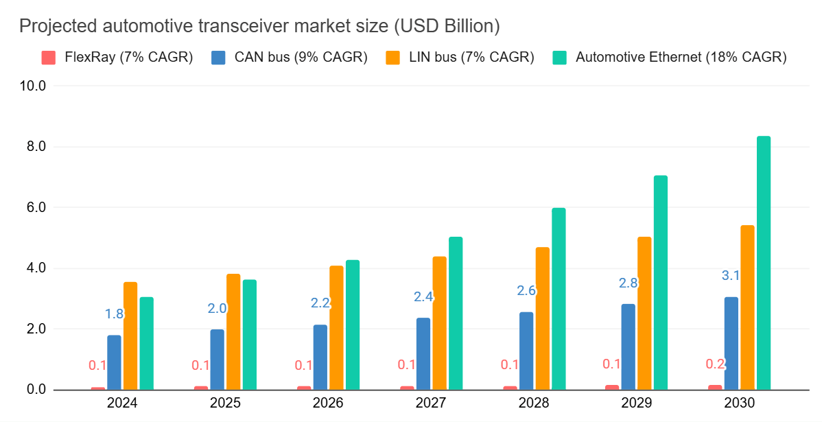
As such, the use of LIN bus transceivers is projected to grow steadily at 5-10% per year, in line with the projected growth of CAN bus transceivers. As evident, this projected growth is in parallel with the expected rise of Automotive Ethernet, indicating a belief that LIN (and CAN) will continue to play key roles in automotives for many years to come.
The projected market size is based off various online sources/reports - for an overview, see this Google Sheet. It should be stressed that it is incredibly difficult to estimate the transceiver market, so all numbers should be considered accordingly. Further, the market size absolute value estimates per transceiver type will most likely differ massively from the volume, with LIN bus transceivers e.g. being very low cost vs. CAN bus or Automotive Ethernet transceivers.
To illustrate the uncertainty on projections like this, you can also compare vs. another reported projection (focused on #nodes) below:
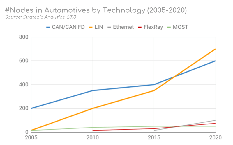
However, with the rise of LIN also comes increased scrutiny in regards to cyber security. LIN faces similar risk exposures as CAN - and since LIN plays a role in e.g. the seats and steering wheel, a resolution to these risks may be necessary.
The future automotive vehicle networks are seeing a rise in CAN FD, FlexRay and automotive Ethernet. While there's uncertainty regarding the role each of these systems will play in future automotives, it's expected that LIN bus clusters will remain vital as the low cost solution for an ever increasing demand for features in modern vehicles.
As part of designing a more inclusive wording for LIN bus, the CiA/ISO/SAE agreed wording will transition to commander/responder. As such, this will be the de facto standard wording used in most guidelines and LIN bus specifications going forward.
Alternative wording includes LIN publisher/subscriber, which is used e.g. in our CANedge documentation.
LIN bus applications
Today, LIN bus is a de facto standard in practically all modern vehicles - with examples of automotive use cases below:
- Steering wheel: Cruise control, wiper, climate control, radio
- Comfort: Sensors for temperature, sun roof, light, humidity
- Powertrain: Sensors for position, speed, pressure
- Engine: Small motors, cooling fan motors
- Air condition: Motors, control panel (AC is often complex)
- Door: Side mirrors, windows, seat control, locks
- Seats: Position motors, pressure sensors
- Other: Window wipers, rain sensors, headlights, airflow
Further, LIN bus is also being used in other industries:
- Home appliances: Washing machines, refrigerators, stoves
- Automation: Manufacturing equipment, metal working


Example: LIN vs CAN window control
LIN nodes are typically bundled in clusters, each with a master that interfaces with the backbone CAN bus.
Example: In a car's right seat you can roll down the left seat window. To do so, you press a button to send a message via one LIN cluster to another LIN cluster via the CAN bus. This triggers the second LIN cluster to roll down the left seat window.
LIN bus OSI model & standards
In order to better understand LIN bus (as standardized in ISO 17987), let us consider the 7-layer OSI model.
Similar to CAN bus, LIN bus specifies the physical layer and data link layer. This is to be expected of a 'lower layer protocol'.
However, in contrast to CAN bus, LIN also details aspects related to the transport layer and application layer.

LIN physical layer [ISO 17987-4]
Below we outline key properties of the LIN bus physical layer:

1: Master/slave architecture
A LIN bus has a single LIN master and up to 15 LIN slave nodes (up to 16 nodes in total), forming a LIN cluster.
Every LIN node has a 'slave task' (for ignoring, sending and receiving data), while the LIN master also has a 'master task' responsible for scheduling all communication on the bus, ensuring deterministic and collission-free operation.
The LIN master often acts as a gateway between a LIN cluster and a vehicle CAN bus. As in CAN, all LIN node roles are handled by Electronic Control Units (ECUs), each including a microntroller, serial interface (SCI) and LIN transceiver.
2: Single wire
Data transmission is done via a bidirectional single wire architecture based on K-line principles (ISO 9141). Every LIN node is connected to the single wire LIN bus (LIN), the supply voltage (VBAT) and a shared ground (GND). LIN allows for 12V and 24V systems across a max bus length of 40 meters with bit-rates of 1 to 20 kbit/s (typically 9.6, 10.4 or 19.2 kbit/s).
Inside every LIN node, the LIN and VBAT lines are connected with a pull-up resistor (30 kΩ) and a diode. In addition, a stronger pull-up resistor (1 kΩ) is implemented externally near the LIN master. The weak LIN slave resistors serve to avoid excessive current draw, while the stronger resistor keeps the LIN bus in a recessive (aka high voltage) state when no nodes are transmitting. If a node looses power (e.g. due to a cable issue), the diodes help avoid 'back-powering' from the LIN bus.
The single wire architecture of LIN helps reduce costs, weight, complexity and power consumption of the LIN clusters. This makes it ideal for use in systems that are rarely used and are not safety critical (e.g. vehicle door controls).
However, the single wire structure also exposes LIN to electromagnetic interference (EMI) and a dependence on VBAT/GND as references to enable data communication. In contrast, CAN uses a dual wire architecture (CAN high/low), making it resistant to EMI. CAN also does not necessarily depend on VBAT/GND for communication.


3: LIN signaling
LIN enables bit-wise communication by switching the single wire LIN bus from high (recessive, logic 1) to low (dominant, logic 0). As explained above, the default state is recessive and requires that no nodes are transmitting. The supply voltage and ground are used as references for the bus level.
For receiving LIN nodes, a bus level above 60% of the VBAT voltage level is interpreted as a logic 1 - while a level below 40% is considered a logic 0. For transmitting LIN nodes, these thresholds are 80% and 20% instead. This discrepancy in thresholds helps ensure the sender produces a stronger signal than what is minimally required by the receiver to account for e.g. voltage drops or signal degradation. Notice that the actual LIN bus voltage (VSUP) may differ from the externally provided battery voltage (VBAT).
LIN data link layer [ISO 17987-3]
In this section we cover key topics related to the LIN bus data link layer.
1: Deterministic scheduling
A LIN master requests data from each LIN slave periodically as part of a schedule table. A single targeted LIN slave responds with data when polled (avoiding the need for arbitration). A schedule defines which frames are to be transmitted during which 'frame slot' timings. A frame slot begins when a frame transmission is initiated and lasts until the next scheduled frame begins. Importantly, this time slot must be defined as an integer multiple of the LIN cluster time base (typically 5 ms or 10 ms).
As described previously, the LIN master has both a 'master task' and 'slave task' and the master node may thus also provide the response payload to its own header request. This is e.g. used in LIN diagnostics and node configuration.
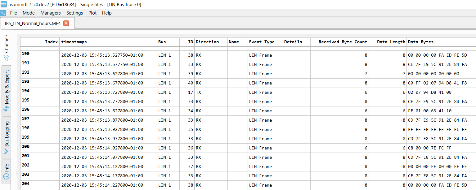
If we record LIN frames with e.g. a CANedge, the result looks similar to raw CAN data - i.e. timestamped LIN frames with IDs and data payloads. The fact that the ID and payload may come from separate nodes is not visible (or relevant) in this context.
2: The LIN message frame format
In simple terms, the LIN bus message frame consists of a header and a response.
Typically, the LIN master transmits a header onto the LIN bus to trigger a single LIN slave, which sends up to 8 data bytes in response. The LIN frame can be illustrated as below:

Sync Break Field (SBF): The Sync Break Field (SBF) is minimum 13 + 1 bits long, with the last bit reflecting a delimiter. The field acts as a 'start of frame' notice to all LIN nodes on the bus.
SYNC Field: The 8 bit SYNC field has a fixed data value of 0x55 (binary 01010101). This allows the LIN slaves to determine the time between rising/falling edges and thus the baud rate used by the LIN master, allowing them to stay in sync.
Notice that we refer to the SYNC field as 8 bits, even though the length of the full byte field is 10 bits. This is because all LIN byte fields are structured with a dominant start bit and recessive stop bit (except for the SBF). When we count the number of bits, we ignore the start/stop bits as they do not factor into e.g. calculating the value of a field. This is evident if you look at the SYNC field, as the value 0x55 is found by taking the binary sequence of 01010101b (the 1st transmitted bit is the LSB, while the 7th bit is the MSB).
Protected ID Field (PID): The Protected ID Field (PID) contains the frame ID (6 bits, allowing for 64 unique IDs), followed by 2 parity bits. This acts as an identifier for each LIN message sent. LIN slaves verify the validity of the ID based on the parity bits and react via below:
- Ignore the subsequent data transmission
- Listen to the data transmitted from another node
- Publish data in response to the header
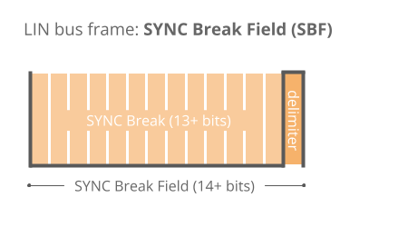
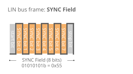
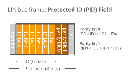
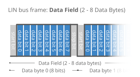
Data Field: When a LIN slave is polled by the master, it can respond by transmitting 2 to 8 bytes of data. The data bytes contain the actual information being communicated in the form of LIN signals using Intel byte order. The data length can be customized, but it is typically linked to the ID range:
- ID 0-31: 2 data bytes
- ID 32-47: 4 data bytes
- ID 48-63: 8 data bytes
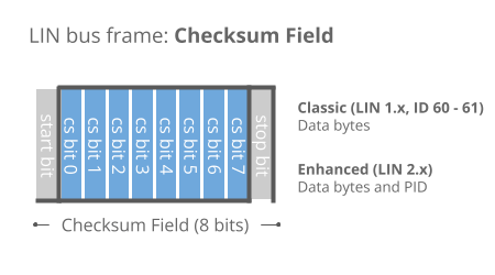
Checksum Field: As in CAN, a checksum field ensures the validity of the LIN frame. The classic 8 bit checksum is based on summing the data bytes only (LIN 1.x), while the enhanced checksum algorithm also includes the identifier field (LIN 2.x). IDs 60-61 always use classic checksum.
The LIN bus parity bits are calculated based on the ID bits. The methodology is described in the LIN bus protocol specification. To illustrate this in practice, we have created a simple parity bit calculator in Google Sheets, replicating the full LIN bus parity bit table from the specification.
LIN bus parity bit calculatorSince the low cost LIN slaves are often low performing, delays may occur. To mitigate this, inter byte space can optionally be added as illustrated. Further, between the header and response, there is a 'response space' that allows slave nodes sufficient time to react to the master's header.

Logging LIN bus data
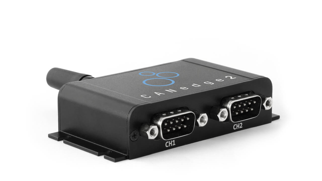
The CANedge lets you easily log LIN bus data to an 8-32 GB SD card. Simply connect it to your LIN application to start logging - and process the data via free software/APIs.
For example, the free asammdf GUI/API lets you decode your LIN data to physical values using DBC/LDF files and e.g. plot your LIN signals.
LIN bus data loggers3: LIN frame types
Multiple types of LIN frames exist, though in practice the vast majority of communication is done via 'unconditional frames'. Each LIN frame type follows the same basic structure - and only differ by timing or content of the data bytes.
Below we briefly outline each LIN frame type:


Unconditional Frames
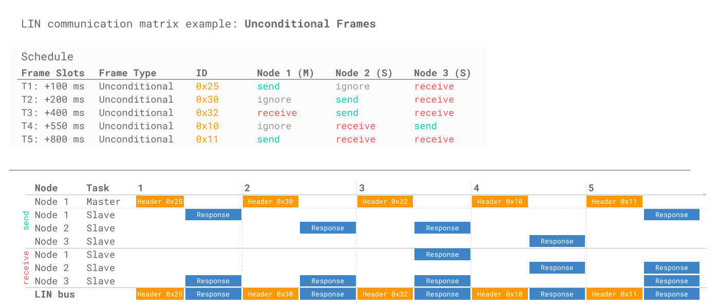
This is the default form of communication where the master sends a header to request information from a specific slave, which responds with data. Note that the LIN master may itself transmit data in response to specific headers.
To illustrate this consider below LIN communication matrix example. The example LIN cluster includes three LIN nodes, with Node 1 acting as the LIN master:
Event Triggered Frames
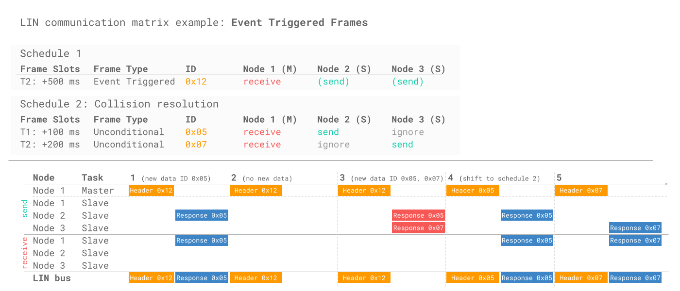
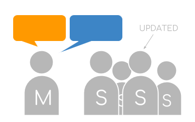
This frame type enables increased responsitivity in the LIN cluster and can e.g. be used to monitor door knobs (where it is rare for multiple knobs to change state simultaneously). The master requests data from multiple slaves. A slave responds if its data has been updated, with its protected ID (PID) in the 1st data byte, serving the role of a node source address. If multiple slaves respond, a collision occurs and the master switches temporarily to unconditional frames in order to request data individually from each LIN slave. Note that event triggered collisions are not considered LIN errors by any nodes on the bus.
Below example illustrates how Node 2 and 3 may respond with data to the same header ID - and how this can result in a collision, causing the master to shift temporarily to another schedule. Note that the example explicitly states the ID of the response payloads to reflect that the PID is contained in the 1st byte:
Sporadic Frames
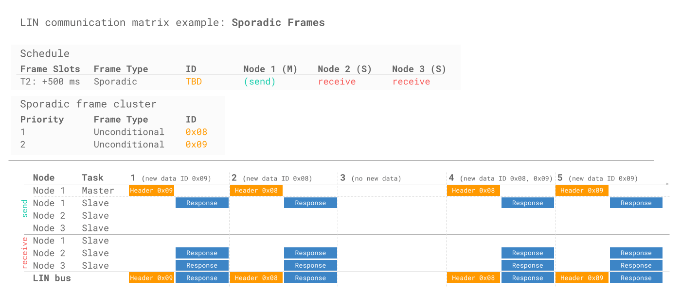
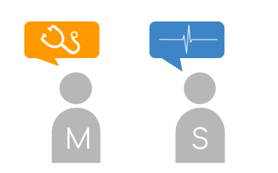
Sporadic frames allow the LIN master to transmit data onto the LIN bus in a dynamic way. Specifically, a sporadic frame corresponds to a group of unconditional frames that share the same slot in the deterministic schedule. If a signal in one of these underlying frames has updated data, the LIN master will transmit it onto the bus in this slot - and otherwise the slot is silent. If multiple frames have new data, the LIN master transmits the frame with the lowest ID (highest priority).
Below, the LIN master sends a header and responds to it itself if new data is available from one of two frames (ID 0x08, 0x09) - allowing Node 2 and 3 to receive the data. ID 0x08 is sent first if both frames have new data due to its higher priority:
Diagnostic Frames
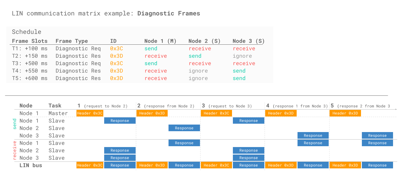
In LIN 2.x, IDs 60-61 are used for reading diagnostics from the master or slaves. Frames always contain 8 data bytes. ID 60 (0x3C) is used for the master request (where the master sends both header and response), 61 (0x3D) for the slave response. The LIN master targets a specific LIN slave by including the Node Address (NAD) in the 1st byte of the response. A multi-frame segmented response is possible. Payloads are defined as per ISO 15765-2 (ISO TP) and ISO 14229 (UDS).
Below, the master sends a diagnostic request to Node 2, which responds with a single frame. The master then sends a request to Node 3, which sends a segmented response across two frames.

User Defined / Reserved Frames
ID 62 (0x3E) is used for user-defined frames, which may contain any type of information. Reserved frames have ID 63 (0x3F) and must not be used in LIN 2.x conforming LIN networks
4: LIN errors - detection & handling
While the LIN protocol is designed for robustness, errors may arise. ISO 17987-3 specifies how to detect LIN errors and how nodes may respond. The LIN master monitors the overall LIN cluster to determine if some nodes are faulty, while each individual LIN slave node may also monitor its own interaction with the LIN bus.
All LIN slaves must transmit a mandatory 'statusbit' aka 'response_error' signal within the payload of one of their unconditional frames. This bit is by default set to 0 (dominant), but if the LIN slave detects an error in the previous communication cycle, it will set the bit to 1. For example, a LIN based battery sensor might encode this as bit 47 within an unconditional frame carrying information on the battery state of charge.


Below we provide an overview of LIN errors by type:
- Checksum Error: A LIN node detects an error if it calculates a different checksum vs. the one in the LIN frame
- Synchronization Error: If a LIN node determines that its bit-rate deviates too much from the bus based on the SYNC field
- Timeout Error: If a response is not transmitted immediately after a header (except for event triggered frames)
- Parity Error: If the parity bits are incorrect, the receiver nodes detect an error and typically ignore the header
- Framing Error: If a LIN frame field deviates from the expected format it reflects a framing error
- Bit Error: A transmitter detects an error if it observes that the LIN bus level differs from what is being transmitted
LIN transport layer and diagnostics [ISO 17987-2]
The LIN bus protocol specifies a transport layer in ISO 17987-2, which is very similar to the ISO-TP transport layer used for CAN bus (ISO 15765-2). The nearly identical design of the transport layers simplify e.g. diagnostics in vehicles that combine CAN backbones and LIN clusters.
Specifically, diagnostic tools can be connected to the CAN backbone of a vehicle and send requests to a LIN master. In turn, the LIN master requests information from relevant LIN slaves and feed the responses back to the tester via the CAN bus.
As with ISO 15765-2, diagnostic communication can be done via Single Frames (one request, one response) or via multiple frames using a First Frame (FF) and Consequtive Frames (CF). Note that LIN TP does not use flow control frames and that the NAD must be contained in the 1st byte of the response.


As in UDS on CAN, the LIN master includes a service identifier (SID) in the request, while the LIN slave includes the response service identifier (RSID) in the response (equal to the SID + 0x40). The LIN protocol specifies a list of SIDs as per the table.
Below we provide an example LIN bus trace showing a master sending diagnostic requests to two LIN bus slaves with node addresses (NADs) 0x01 and 0x02, respectively. In the example, the UDS SID 0x22 (Read Data by Identifier) is used. Node 0x01 responds with a single-frame response, while node 0x02 responds with a multi-frame response.

A key aspect of LIN is not only saving costs, but also power.
To achieve this, each LIN slave can be forced into sleep mode by the master sending a diagnostic request (ID 60) with the first byte equal to 0. Each slave also automatically sleeps after 4 seconds of bus inactivity.
The slaves can be woken up by either the master or slave nodes sending a wake up request. This is done by forcing the bus to be dominant for 250-5000 microseconds, followed by a pause for 150-250 ms. This is repeated up to 3 times if no header is sent by the master. After this, a pause of 1.5 seconds is required before sending a 4th wake up request. Typically nodes wake up after 1-2 pulses.

LIN Description File (LDF) [ISO 17987-1]
To quickly set up LIN bus networks, off-the-shelf LIN nodes come with Node Capability Files (NCF). The NCF details the LIN node capabilities and is a key part of the LIN topology.
An OEM may combine individual LIN node NCFs into a cluster file, referred to as a LIN Description File (LDF). The LIN master can set up and manage the LIN cluster based on this LDF as the file describes e.g. the time schedule for headers.
Note that LIN nodes can be re-configured via diagnostic frames to change e.g. the frame IDs or NADs.
If you are familiar with CANopen, you may see parallels to the Device Configuration File used to pre-configure CANopen nodes - and the role of Service Data Objects in updating them.
Importantly, the LDF also includes decoding details for all LIN frames in the cluster. As a result, the LDF plays a similar role in LIN bus data analysis as the DBC file does for CAN bus.
To learn more, see our intro to LIN Description Files.

LIN bus data logging - use case examples
LIN bus data logging is relevant across various use cases:

Vehicle CAN/LIN development
Logging CAN/LIN data via a hybrid logger is key to OEM vehicle development and can be used in optimization or diagnostics
LIN loggers
Field prototype telematics
CAN/LIN data from automotive prototype equipment can be collected at scale using IoT CAN/LIN hybrid loggers to speed up R&D
j1939 telematics
Predictive maintenance
Industrial machinery can be monitored via IoT CAN/LIN loggers in the cloud to predict and avoid breakdowns via prediction models
predictive maintenance
Rare LIN issue diagnostics
A LIN bus logger can serve as a 'blackbox' for industrial machinery, providing data for e.g. disputes or rare issue diagnostics
can bus blackboxDo you have a LIN data logging use case? Reach out for free sparring!
Contact usBelow we list key considerations for your LIN bus data logging:
To record LIN bus data, you'll need a LIN bus data logger and/or interface. A LIN bus data logger with SD card has the advantage of letting you record data in standalone mode - i.e. during actual usage of the vehicle. An interface, on the other hand, is helpful during e.g. dyno testing of the vehicle functionality. For standalone LIN loggers, it's key that the device is plug & play, compact and low cost - so as to allow it to be used in scale applications across e.g. vehicle fleets.
Often, you will want to combine the LIN bus data with CAN bus data to get a holistic perspective of the vehicle in use - for example:
- How is driving behavior correlated with use of various LIN bus features?
- Do issues arise in the interaction between LIN masters and the CAN bus?
- Are LIN related issues correlated with certain CAN based events?
To combine this data, you will want a hybrid CAN/LIN logger with multiple channels.
Collecting logged LIN bus data can be a hassle if you need to physically extract the data from e.g. large vehicle test fleets. Here, a WiFi/LTE enabled CAN/LIN logger can be a powerful solution. In particular, the CANedge2/CANedge3 can be used as a LIN master/slave for remote data collection, as well as over-the-air support. As an example, you can use the CANedge to collect data from a small LIN cluster of sensors (e.g. HELLA IBS battery sensors) where no other LIN master is available. within the CANedge configuration file you define the schedule for LIN1 and/or LIN2 - allowing the CANedge to record the sensor information from the LIN slaves. If changes are required to the schedule, it can be updated over-the-air in a few clicks.
For more intros, see our guides section - or download the 'Ultimate Guide' PDF.
Need to log LIN bus data?
Get your CAN/LIN logger today!

