
 PLUG & PLAY
Connect up to 4 x CAN to receive / transmit the data via 1 x CAN (or USB) - no configuration required
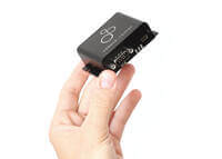
 COMPACT
7 x 2 x 5 CM. 75G. 7 LEDs. Supply via DB9/USB. 5-26 V. Mounting flanges. USB for config/FW and streaming
 PRO SPECS
4 x CAN FD. Galvanic isolation. Silent mode. Zero data loss. 1 ms precision. Error frame support.
 LOG 5 X CAN
Use with CANedge in 'mux-mode' to seamlessly log 5 x CAN buses. Easily 'demux' data via free software
 CAN GATEWAY
Merge/split/filter your CAN buses in 'direct-mode' - incl. configurable CAN ID re-mapping. 100% standalone
 CONFIGURABLE
Configure mode, filters, prescalers, transmit lists, CAN IDs, bit-rates and more via JSON config and GUI
Log 5 x CAN via CANedge + CANmod.router
In mux-mode, traffic from/to the secondary CAN buses is routed through the primary CAN bus via tunnels (CAN frames that transport the original data). Muxed data received by a user CAN node (e.g. CANedge) can be easily demuxed to its original form via software/API tools.

Merge 4 x CAN buses into 1 x CAN bus
In direct-mode, traffic from four secondary CAN buses can be routed onto the primary CAN bus. The data can be filtered (to e.g. reduce busload or remove CAN FD frames) and IDs can be re-mapped (to avoid collisions). This lets you e.g. monitor multiple CAN buses via a single interface.

Split 1 x CAN bus into 4 x CAN buses
An application may use an expensive sensor-to-CAN module. The sensor output should be available on multiple isolated CAN buses. To solve this, the module can be connected to the primary CAN bus with data routed onto all secondary CAN buses.

Control 4 x CAN buses with 1 x CAN bus interface
An application may have a single 'master node' that needs to control multiple isolated CAN buses by transmitting CAN frames. To achieve this, the master node can be connected to the primary CAN bus, with filters controlling what CAN frames are routed from/to each secondary CAN bus.

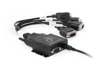
Interface four CAN buses
with just one CAN bus (or USB)
Receive/transmit data from/to 4 x CAN buses via 1 x CAN bus (or USB) - e.g. for use by CAN loggers, ECUs or via USB streaming.
- 4 x CAN (incl. CAN FD) with galvanic isolation
- Power via DB9 (5-26 V and DB9 cables) or USB (5V)
- Independently configure each secondary CAN interface
- Optional silent mode and customizable bit-rates
- Advanced message filters and prescalers
- Configure transmit lists - and/or control via primary CAN
- Support for CAN error frame logging
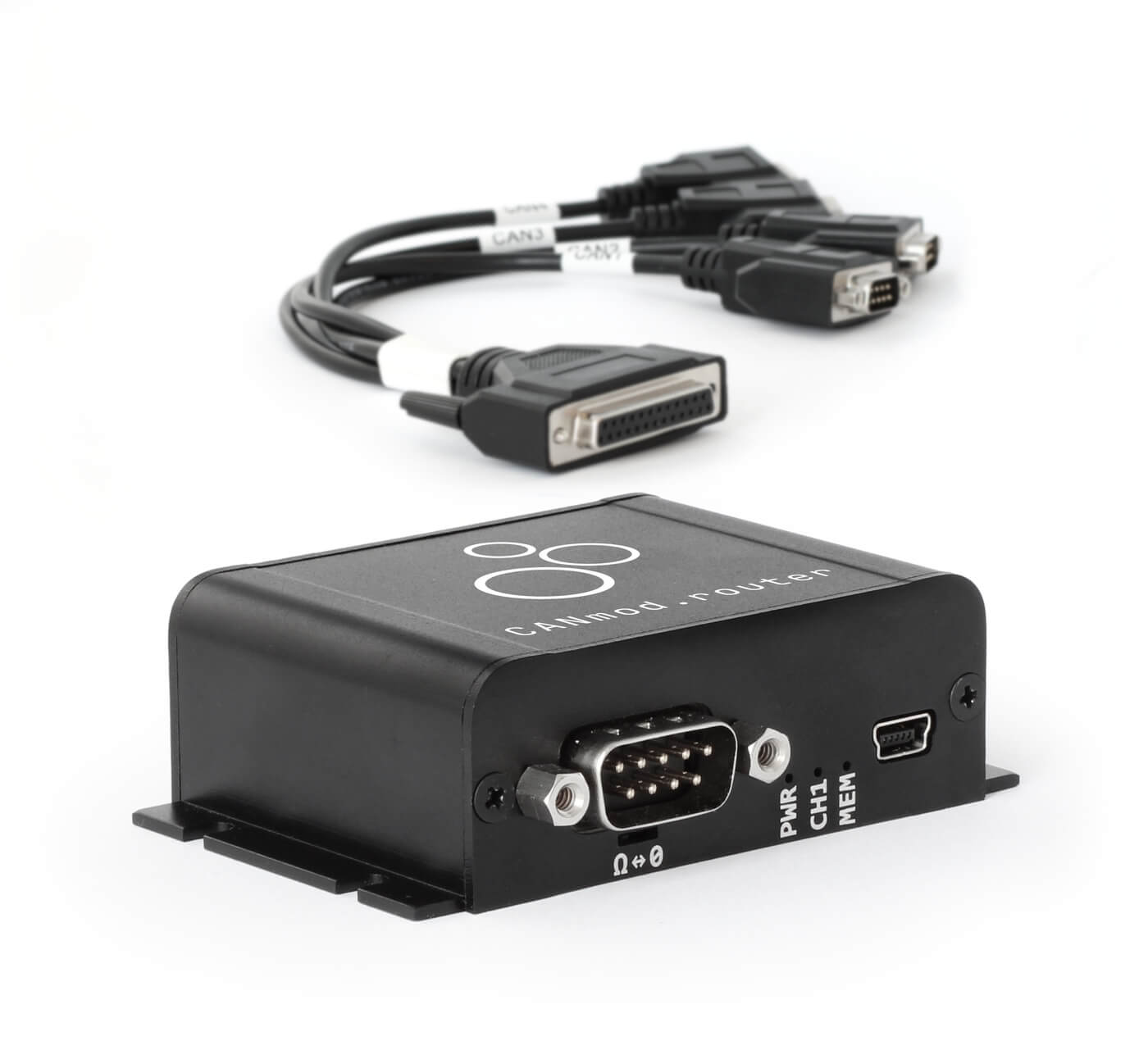
- Quickly connect 4 x CAN via DB25-to-4x-DB9 adapter cable
- Daisy chain multiple modules for 8, 12, 16, ... CAN channels

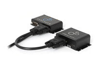
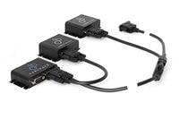
Ex 1: CANedge + CANmod.router
= 5 x CAN bus data logger
The CANedge supports 2 x CAN. By adding a CANmod.router, you can now log 1 x CAN (CH1) + 4 x CAN (CH2) - or beyond.
- Power the CANmod.router via the CANedge 2nd port 5V
- Maximise 4 x CAN throughput via CAN FD routing (mux-mode)
- Easily demux the data via MF4 converters/decoders or Python
- Control transmission on the 4 x CAN via CANedge
- Use daisy chaining to log 1 + 8 x CAN, 1 + 12 x CAN (or beyond)
Tip: Check out muxed/demuxed MF4 sample data below.
Buy Now sample data FAQ use casesWe provide a step-by-step guide for this setup in the CANedge Intro - below we provide a brief recap:
- Connect the CANmod.router to the CANedge 2nd port
- Set the CANedge CAN CH2 bit-rate to 1M/4M
- Set the CANedge 2nd port 5V power supply to enabled
- Optionally set bit-rates and filters on the CANmod.router
The CANedge can now record 1 x CAN (via CH1) + 4 x CAN (via CH2). The regular CH1 data and 'muxed' CH2 data is stored by the CANedge in MDF log files (*.MF4).
To DBC decode and analyze the data, you need to first demux the CH2 data. This can be done via the CANedge MF4 converter 'mdf2mdf' - similar to how you 'decompress' compressed MDF files. For details, see below.
Note: If you daisy chain CANmod.routers the process is the same, except that you set unique IDs per device.
Tip: See also our sample MF4 data above.
Let us assume you use a CANedge + CANmod.router to log 1 x CAN (via CH1) + 4 x CAN (via CH2) via mux-mode.
Structure of the muxed MF4 data
If you open the raw MF4 in asammdf, you will see the CAN CH1 data stored as normal - while CAN CH2 contains muxed data. The muxed data comprises CAN FD frames, with the original 4 x CAN-S IDs/data packaged in the payload.
How to demux the data
To work with the data we need to first demux it. The simplest way is to use the MF4 converter 'mdf2mdf'. This can convert raw MF4 files (or MFC/MFE/MFM) to 'finalized' MF4 files. It can be used to decompress, decrypt - and demux - log files. The tool can be used via drag & drop, the CLI and in scripts.
If you open the demuxed MF4 you now see the following:
- CAN CH1 is unchanged
- CAN CH2 is now empty
- CAN CH3-CH6 contain the original 4 x CAN-S frames
This is identical to what you would record if the CANedge itself had more CAN channels, with the original CAN IDs and payloads of the 4 x CAN-S unpacked into CAN CH3-CH6.
Note: You can also use our Python API to demux MF4 files.
Support in other software/APIs
The demuxed MF4 files are fully supported in all our software/API tools, incl. the asammdf GUI, MF4 converters, MF4 decoders, MATLAB, Python, Vector tools, dashboards etc.
Special case: Other device on CH2
You may connect both a CANmod.router and e.g. a CANmod.temp to a CANedge CH2. Here, the demuxed MF4 will include the CANmod.temp data in CAN CH2.
Special case: 2 x CANmod.router
If you need to record 1 + 8 x CAN, you can daisy-chain two CANmod.routers on CH2. One must be configured to use a different CAN ID for the muxed data (e.g. 0x11).
During demuxing, you can specify how to map IDs - e.g. ID 0x10 to CH3-CH6 and ID 0x11 to CH10-CH13.
Ex 2: Merge/split/control your CAN buses
The CANmod.router can be deployed as a 100% standalone CAN bus gateway - allowing you to merge, split or control CAN buses.
- Directly route traffic from/to 4 x CAN and 1 x CAN 'as-is'
- Merge 4 x CAN into 1 x CAN - while retaining isolation
- Split 1 x CAN into 4 x CAN for e.g. sensor repetition or control
- Manage CAN traffic via ID filters/prescalers
- Re-map CAN IDs from secondary CAN buses to avoid collisions
- Fully customize all 5 x CAN channel bit-rates
- Configure everything easily via GUI config editor
Ex 3: Stream 4 x CAN FD via USB in SavvyCAN/Python
You can also interface the 4 x CAN buses via USB - making the CANmod.router the best value/cost CAN interface on the market.
- Receive/transmit data from 4 x CAN FD via USB
- Stream 6,000+ frames/second without frame loss
- Power the CANmod.router via USB for easy installation
- Stream raw / DBC decoded data in free SavvyCAN GUI
- Develop any integration via free Python API
- Example: Visualise decoded data in Grafana-MQTT dashboards
Let us assume you wish to stream 4 x CAN in SavvyCAN:
- Connect the CANmod.router via USB to your PC
- Connect the 4 x CAN via the DB25 connector
- In SavvyCAN, select the device via our plugin
- Add the 4 x CAN as 'connections' one-by-one
You will now see the raw data from each of the 4 x CAN.
Note that our SavvyCAN plugin (and Python API) demuxes the data in real-time - meaning you receive/transmit data as-if directly connected to the 4 x CAN buses.
For details on USB streaming, see the CANmod Intro.
If you need to stream CAN bus data via USB you can use both the CLX000 and CANmod.router.
For pure streaming use cases, we recommend the CANmod.router as it offers multiple advantages:
- It can be powered via USB while streaming - the CLX000 has to be powered via the DB9 (7-32V)
- It offers 4 x CAN interfaces vs. 1 x CAN for the CLX000
- It supports CAN FD on all 4 interfaces
- It can handle 6,000+ frames/second vs. 1,000+ frames/second for the CLX000
- It provides flanges for easier mounting in the field
- It offers advanced configuration of e.g. bit-rates, filters
Check out our tech specs, use cases or FAQ - or buy now!
Do you have any questions?
Contact us


| GENERAL | |
|---|---|
| Functionality | The device routes data from four isolated CAN buses (incl. FD) to one primary CAN bus (or USB) |
| Included | CANmod.router module and USB dust cover (DB25-to-4x-DB9 adapter and USB adapter not included) |
| Firmware | Supports free firmware updates via USB for adding features |
| Configuration | Configuration files based on the popular open source JSON schema concept (similar to the CANedge) |
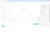
| Software | Free open source editor tool for easy device configuration (offline/online version available) |
| Free open source SavvyCAN GUI for streaming of raw / DBC decoded data via USB | |
| Free open source Python API for streaming of raw / DBC decoded data via USB | |
| Safety | CE, FCC, IC and RoHS certified (see the Docs for certificates) |
| Warranty | 1-year warranty |
| Support | Free, fast & high quality support |
| Origin | Denmark |
| ROUTER MODES | |
| Mux-Mode | Traffic from/to secondary CAN buses is muxed and transported through 'tunnels' via primary CAN bus |
| Demuxing done via software/API tools to restore original CAN frames (channel IDs, CAN IDs, payloads) | |
| - CANmod software/API with demuxing: SavvyCAN, USB Python API | |
| - CANedge software/API with demuxing: MF4 Python API, mdf2mdf (and hence all CANedge tools) | |
| CAN BUS (CAN-S) | |
| Channels | 4 x CAN channels (incl. CAN FD support) |
| Isolation | Basic galvanic isolation (easily connect CAN buses not subject to high voltage differences) |
| Standard | ISO 11898: Compliant with CAN (between 5K and 1 Mbit/s baud rates) and CAN FD (1M, 2M, 4M, 5M) |
| Protocols | Receive/transmit raw data from/to CAN based protocols (J1939, CANopen, NMEA 2000, OBD2, UDS, ...) |
| Identifiers | Compliant with CAN specifications 2.0A (11-Bit ID) and 2.0B (29-Bit ID) |
| Retransmission | Retransmission of frames that have lost arbitration or been disturbed by errors |
| Transceiver Protection | Protection: +/- 25kV HBM ESD, +/-12kV IEC ESD, +/-14 V bus fault, short circuit |
| Common mode input voltage: +/-12V | |
| TXD dominant timeout (prevents network blocking in the event of a failure) | |
| CAN BUS (CAN-P) | |
| Channels | 1 x CAN channel (incl. CAN FD support) |
| Modes | The device can either broadcast the data onto the CAN bus - or provide it on-request |
| Standard | ISO 11898: Compliant with CAN (between 5K and 1 Mbit/s baud rates) and CAN FD (1M, 2M, 4M, 5M) |
| Identifiers | Compliant with CAN specifications 2.0A (11-Bit ID) and 2.0B (29-Bit ID) |
| Termination | Termination can be toggled via switch below DB9 connector |
| Retransmission | Retransmission of frames that have lost arbitration or been disturbed by errors |
| Transceiver Protection | Protection: +/- 25kV HBM ESD, +/-12kV IEC ESD, +/-14 V bus fault, short circuit |
| Common mode input voltage: +/-12V | |
| TXD dominant timeout (prevents network blocking in the event of a failure) | |
| CONFIG (CAN-S) | |
| Independence | Each secondary CAN channel can be independently configured (router mode is set globally) |
| Bit-Rate | Select between standard bit-rates (5K to 1M) or use custom bit-timing (configure per channel) |
| Bit-Rate Auto-Detect | Bit-rates can be set manually (auto-detection pending FW) |
| Silent Mode | Configurable silent mode: Restricted (acknowledge only) or monitoring (zero transmission) |
| Filters | 32 regular/extended ID filters per channel (mask, acceptance, rejection) |
| Prescalers | Prescale CAN frames to record e.g. by time (per X ms) or by data (e.g. if byte X or Y changes) |
| Transmit | Transmit lists of up to 16 CAN frames per channel (single-shot/periodic) |
| Transmission can also be directly controlled from the CAN-P interface | |
| CAN Error Frames | Support for logging CAN error frames (bit-stuffing, form, CRC, bit, acknowledgement) |
| CONFIG (CAN-P) | |
| Bit-Rate | Select between standard bit-rates (standard: 5K to 1M, FD: 1M to 4M) or use custom bit-timing |
| Identifier Customization | Individually configure each CAN ID (11-bit or 29-bit) |
| OTHER | |
| Precision | Cross-channel precision of 1 ms |
| Frames/Second | Mux-mode: Route 6,000+ frames/second (Classical CAN) - see FAQ for details |
| ELECTRICAL | |
| Input Supply | +5V to +26V DC via the DB9 connector (power via pin 1 or pin 9) |
| Alternatively power via USB (for updating firmware/config or for streaming data in real-time) | |
| Power Consumption | Extremely low (<1W) - no risk of battery drainage |
| Protection | Reverse voltage protection on CAN-bus supply |
| Transient voltage event protection on supply lines | |
| MECHANICAL | |
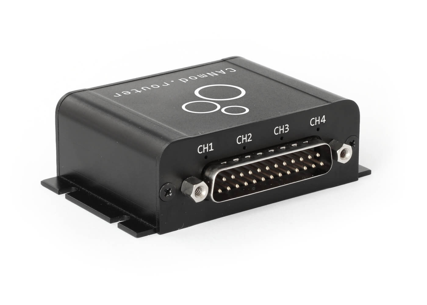
| Enclosure & Weight | Compact aluminium enclosure: 65 x 48 x 24 mm (W x L x H excl. flanges & connectors). 75 grams |
| Connector (Front) | 1 x Standard D-sub 9 (DB9) connector |
| Connector (Back) | 1 x D-sub 25 (DB25) connector |
| Pin-Out | See the product manual for the DB9/DB25 connector pin-outs |
| USB | Standard mini USB connector for config/FW updates and streaming (USB cable available as option) |
| LEDs | Module status via 7 external LEDs: Power, CAN-P, Memory, CAN-S1, CAN-S2, CAN-S3, CAN-S4 |
| Temperature | Operating temperature: -25degC to +70degC |
| IP Rating | IP Rating 40 |
| Mounting | Module can be mounted via e.g. velcro strips or mounting kit |
The CANmod.router can be installed standalone in any CAN bus system - including e.g. as an add-on for the CANedge. Further, it can be used as a powerful 4 x CAN FD to USB interface.

OEM CAN bus telematics with 5 x CAN channels
Need to collect data from 5 x CAN buses across your vehicle fleet?
As an automotive OEM, you may want to use the CANedge3 to collect CAN data and upload it via 3G/4G to your own AWS S3 bucket. But what if you need to log e.g. 5 x CAN per vehicle? Here you can simply add the CANmod.router to the CANedge 2nd port in mux-mode to log 1 + 4 x CAN. Using the DB25-to-4x-DB9 adapter, you can quickly connect the 4 x CAN using our standard DB9 adapters. When the MF4 log files are uploaded to your cloud, they can be automatically 'demuxed' and DBC decoded via Lambda functions for e.g. creation of Parquet data lakes and Grafana dashboards.
Merge 4 x CAN FD buses into 1 x Classical CAN bus
Need to merge CAN buses during ECU development?
A vehicle OEM needs to connect an ECU to multiple CAN buses during development, some of which are CAN FD. The ECU only has one Classical CAN bus interface and is restricted to a 500K bit-rate. To solve this, the CANmod.router can be connected in direct-mode between the ECU and CAN buses, with bit-rates set up to match the various buses - and configured to reject any CAN FD frames from passing through. This enables the OEM to directly interface with the various CAN buses without any ECU modification - while retaining full isolation of the original CAN buses.


Daisy chain 'unconfigurable' sensor-to-CAN modules
Need to daisy chain sensor-to-CAN modules with 'locked' CAN IDs?
Some sensor-to-CAN modules may come with 'locked' CAN message IDs, with no option of configuring the IDs. This in turn makes it impossible to directly daisy chain such sensors on the same CAN bus as their IDs would overlap. To solve this, the CANmod.router can be used as a CAN bus gateway, with the configuration set up to remap incoming CAN IDs from the sensors to ensure unique CAN IDs are assigned for the data routed onto the primary CAN bus. This setup can be scaled to any level by daisy chaining multiple CANmod.router devices.
Development & diagnostics via USB
Need to stream data from/to 4 x CAN / CAN FD via USB?
In development & diagnostics it is often useful to be able to stream data from/to multiple CAN buses in parallel. This normally requires very large/expensive CAN-to-USB interfaces and expensive software tools. However, with the CANmod.router you can stream 4 x CAN (incl. CAN FD) via USB using the 100% free SavvyCAN GUI or Python API. The latter enables any type of custom integration - e.g. visualization in Grafana-MQTT dashboards. Simply power the CANmod.router via USB and connect it to your CAN buses to start streaming. You can of course connect multiple CANmod.routers via separate USB COM ports to stream e.g. 8 x CAN, 12 x CAN etc.


Unlimited CAN channel logging via daisy chaining
Need to log 1 + 8 x CAN, 1 + 12 x CAN or beyond?
By using a single CANedge + CANmod.router, you can easily record 5 x CAN in total. However, you can also go beyond this by daisy chaining 2, 3 or more CANmod.routers. You can add filters/prescalers on each secondary CAN interface to customize what IDs you record (at what frequency), ensuring your CANedge can record everything without frame loss - and that your log file size remains optimized.
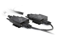
Physical CAN bus extension from remote area
Need to transport CAN data over long distances?
In some use cases, you may want to interface with CAN buses that are far away. For example, you may want to interface with 3 x maritime vessel engines from a bridge (e.g. for integration with a display) - but the cable distance would be 40 meters. It is not recommended to extend existing CAN buses beyond a few meters. However, you can safely deploy one CANmod.router (mux-mode) in the engine room to record the 3 x CAN - and connect it via a 40 meter DB9-DB9 cable to another CANmod.router (mux-mode) at the bridge. The muxed data from the engine room is demuxed in real-time by the bridge device. As a result, you can now interface each engine room CAN bus via the bridge CANmod.router's DB25 connector - as if you had a direct connection. You can even convert the bit-rates of each engine CAN bus in the process or filter/prescale some of the data if preferred.

The CANmod.router is a small device that lets you connect up to four separate, isolated CAN buses (incl. CAN FD) via the DB25 connector. The data from/to these four CAN buses (CAN-S1, CAN-S2, CAN-S3, CAN-S4) is then 'routed' by the module through a single CAN bus (CAN-P) - or via a USB interface.
The device supports two different modes: Mux-mode and direct-mode.
In mux-mode, the data from the four isolated CAN buses is 'transported' via CAN frames onto the primary CAN bus. This works very similar to standard CAN transport protocols like ISO TP (as used in e.g. OBD/UDS). By transporting the data, it is possible to conmbine data from four separate CAN buses without having to worry about e.g. remapping CAN IDs to avoid collisions, as all this is abstracted away via the transport protocol. However, this also requires that the 'receiver' of the data on the primary CAN is able to 'demux' the data to re-create the original CAN frames from the various CAN buses. Our CANedge data logger is therefore ideal for this use case, as the related software/API tools natively enable demuxing of data - making it very easy to use the CANmod.router as an add-on for the CANedge, effectivley enabling you to record 1 x CAN + 4 x CAN (or beyond) with a CANedge + CANmod.router. For details see the CANmod.router Docs
In direct-mode, the data from the secondary CAN buses are routed as-is without any form of transport protocol being involved. This implies that you need to e.g. ensure CAN ID uniqueness on the primary CAN (by re-mapping CAN IDs in the device configuration as needed). However, it has the advantage that no demuxing is required by the receiver, making this mode ideal for standalone deployments. In practice, almost any use case that involves merging/splitting/converting CAN buses can be achieved via the direct-mode of the CANmod.router.
The CANmod.router is an extremely powerful device. Let us illustrate this via common use cases:
CANedge add-on: Log 5 x CAN
The CANmod.router lets you log 5 x CAN via one CANedge. Previously, you had to use 3 x CANedge units with multiple downsides:
- Adding two 'extra' CANedge units is 300-1000 EUR more costly vs adding a CANmod.router
- With three CANedge units, your data is split across three SD cards, MF4 files etc - making data/device management complex
- The best cross-device time sync precision is 400 ms (via internal GPS) - versus 1 ms via the CANmod.router
4 x CAN-USB interface
The CANmod.router can be used as a 4 x CAN-to-USB interface (incl. CAN FD). This is powerful for multiple reasons:
- The CANmod.router is 50%+ lower cost vs. comparable CAN-USB interfaces
- The CANmod.router is 50%+ more compact vs. comparable CAN-USB interfaces
- The CANmod.router comes with 100% free software/API tools for streaming
- The software/API tools let you DBC decode and visualize data in real-time
- SavvyCAN lets you receive/send data from/to all 4 x CAN buses in one GUI window
- The Python API enables easy integration with custom systems like Raspberry Pis - e.g. for field deployments
CAN bus gateway
The device can be used standalone in direct-mode to enable practically any routing use case across multiple CAN buses. This has a number of benefits:
- You drastically reduce costs vs. other routes (e.g. in development time, wiring, sensors, ...)
- The deployment can be quickly modified via a simple configuration change
- You can quickly prototype the implication of more expensive, structural network changes
- Via galvanic isolation, the router provides a safe way of merging buses
In short, the CANmod.router offers a ton of functionality in a single device.
Note: The numbers stated below are preliminary/indicative and may change.
A common use case is to log 5 x CAN with a CANedge + CANmod.router - here we discuss performance considerations.
CAN channels
You can record any number of CAN channels with one CANedge by adding a daisy chain of CANmod.routers. You can add e.g. 10 x CANmod.routers to log 40+ CAN channels - the limitation is purely related to the combined frames/second (see below).
If you daisy chain CANmod.routers on the CANedge 2nd port, you may need to consider if the 5V supply is sufficient. If all CAN-S interfaces are in 'Monitoring' mode then it will suffice. If not, you may need to consider a separate supply.
Frames/second considerations
The primary thing to consider is the total #frames/second you need to record across all of the CAN channels.
We recommend to stay below 6,000 frames/second in total (after filters/prescalers).
- 90%+ of use cases will have far below 6,000 frames/second across 5 x CAN - even without filters/prescalers
- Channel distribution is not relevant - it could e.g. be 1 x 4,000 frames/second + 4 x 500 frames/second (or any other mix)
- The performance limit is higher - the 6,000 frames/second is mainly based on practical considerations (see below)
- During the split-second creation of a new log file, the CANedge may loose frames if recording at very high data rates
Using filters and prescalers
Even if the combined #frames/second exceeds the limit, this is not necessarily an issue at all. The CANmod.router lets you configure filters and prescalers across each of the secondary CAN channels (similar to the CANedge). This means that you can record 4 x CAN channels that have a combined load of e.g. 10,000 frames/second - as long as you filter & prescale this sufficiently.
Practical considerations on file size, SD storage and upload speed
If you do record ~6,000 frames/second 24/7 you will accumulate 5+ MB/min (compressed), 300+ MB/hour, 7+ GB/day and 200+ GB/month. In other words, a CANedge with 32 GB will only store ~5 days of data before it deletes old files to free up space.
Of course, you can get around this by using a CANedge2/3 to upload log files when created. However, in practice the upload speed may make it difficult to offload data fast enough if you go beyond 6,000 frames/second (in particular in intermittent coverage).
To recap: We recommend to stay below 6,000 frames/second - and to use filters, prescalers and compression to optimize file size.
You may wonder if your use case can be handled by the CANedge + CANmod.router. The short answer is "yes!" in 95%+ of cases.
As explained, the limitation to consider is the #frames/second you need to log (after filters/prescalers) across all CAN buses.
To determine this, we recommend the below process:
- Record 5 min from each CAN bus with no filters via the CANedge CH1
- Convert each MF4 log file to CSV via our mdf2csv converter
- Open each CSV in Excel and note the #frames (count) and #seconds (last vs. first)
- Sum up the #frames/second across all CAN channels
If your total #frames/second is below ~6,000 then you are OK and it is mainly a matter of optimizing file size when you deploy.
If your total #frames/second is above ~6,000 then review each CAN bus to determine what messages can be filtered out or prescaled. After accounting for this, revisit the combined #frames/second to see if it is within the limits.
You can of course contact us for sparring on this.
We offer a number of useful adapter cables as options for the CANmod.router:
DB9-DB9/DB9 (Y splitter): This can e.g. be used to connect a CANmod.router to a CANedge 2nd port, enabling the CANedge to record 4 x CAN on CAN CH2. Further, you can add additional Y-splitters if you need to daisy chain more CANmod devices.
DB25-to-4x-DB9: This adapter can be used with the CANmod.router to enable the connection of four separate CAN buses. The advantage of this adapter is that the DB9 pinouts match the CiA 303-1 standard (like the CANedge DB9 connectors), meaning that you can directly use all of our standard DB9 adapter cables, such as our DB9-OBD2, DB9-J1939, DB9-M12 etc. You can even use dual-channel adapters like our J1939-DB9/DB9, OBD2-DB9/DB9 and DT06-DB9/DB9 adapters.
Do you have any questions?
Contact us